Method of exchanging information between two networks operating under different routing protocols

a technology of routing protocol and information exchange, applied in the direction of data switching network, digital transmission, electrical equipment, etc., can solve the problem of quite significant burden on the first routing device, and achieve the effect of reducing work load

Inactive Publication Date: 2010-01-21
SAFRAN ELECTRONICS & DEFENSE
View PDF4 Cites 33 Cited by
  • Summary
  • Abstract
  • Description
  • Claims
  • Application Information

AI Technical Summary

Benefits of technology

[0013]Thus, the identification messages issued by the first routing element comprise both conventional identification message information and information enabling the routing table of the second routing element to be updated. Because this information, which ought normally to appear in the update messages, is incorporated in the identification messages, there is no longer any need for the update messages. The work load on the first routing element is then relatively small and the volume of information transiting between the first routing elements and the second routing elements is small. The neighborhood identification fields of the identification messages issued by the first routing elements also enable the second routing element to determine which of the two first routing elements is actually connected to the first network.
[0015]Since update messages are neither issued nor used by the first routing elements that possess respective static routing tables, and possibly default routes for information having the second network as its destination, there is no need for the second routing element to send update messages to the first routing element, thereby making it possible to further reduce the work load on the first routing element and the volume of information exchanged over the link between the first routing element and the second routing element.

Problems solved by technology

Nevertheless, such exchanges of information would burden the first routing devices in quite significant manner, particularly since as a general rule such routing devices have computing resources that are relatively limited.

Method used


Image

  • Method of exchanging information between two networks operating under different routing protocols
  • Method of exchanging information between two networks operating under different routing protocols

Examples


Embodiment Construction

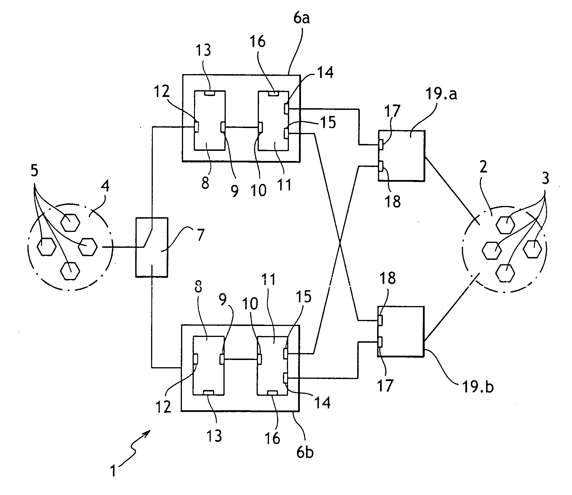
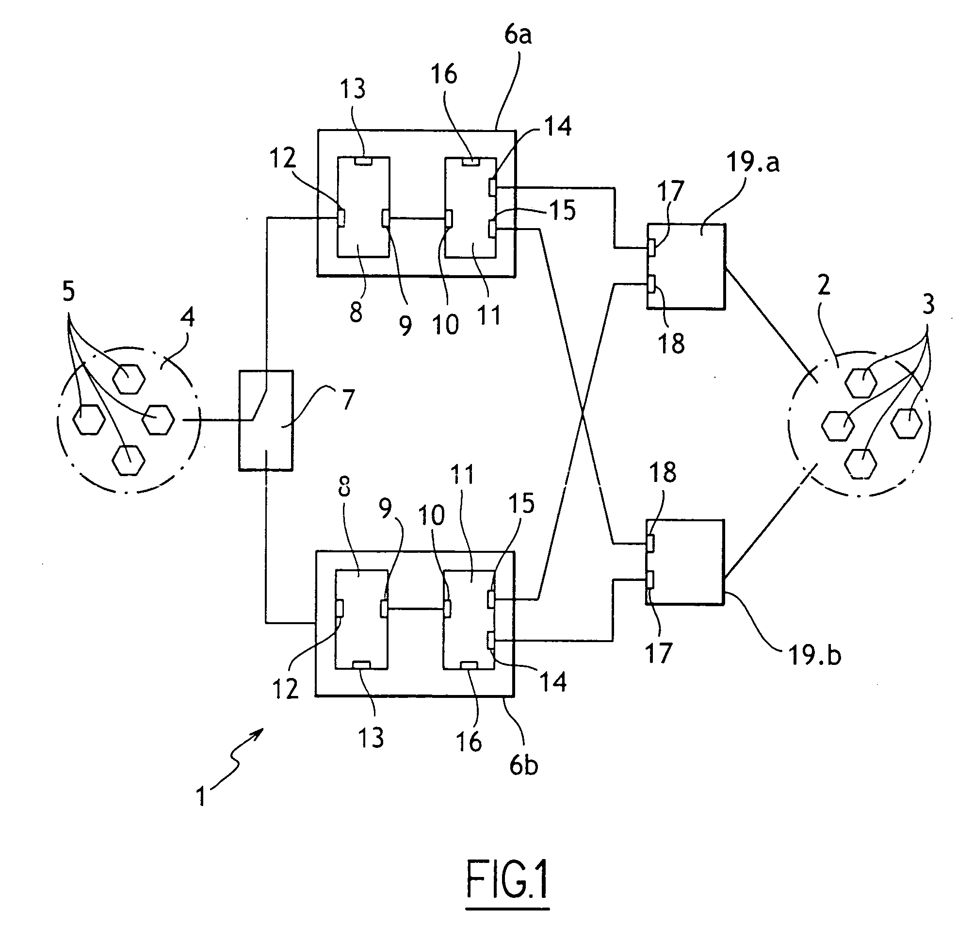
[0018]With reference to the FIGURE, the method of the invention is described below as applied to a network given overall reference 1 and located on board an aircraft, for example.

[0019]The network 1 comprises a network 2 having network elements 3 such as servers or other computer devices, and a network 4 comprising network elements 5 such as servers or other computer devices. In this case, the network 2 is a public network used by the crew to obtain information concerning the flight, the passengers, the airports visited, . . . , and also to give passengers access to entertainment means. In this case the network 4 is used to operate the airplane itself. The network 4 is a highly secure network, while the network 2 is a less secure network.

[0020]Two protection and routing elements 6a and 6b are connected to the network 1 via a selector device 7.

[0021]Each protection and routing device 6 is itself known and comprises a router 8 with an internal interface 9 connected to an internal inte...


PUM


Abstract

A method of exchanging information between a first network implementing a routing protocol using static routing tables and a second network implementing a routing protocol using dynamic routing tables and including stages of exchanging identification messages and of exchanging routing table update messages, the method comprising the steps of: a first routing element associated with the first network issuing to a second routing element associated with the second network identification messages containing identifiers of network elements to which the first routing element knows it is connected either directly or indirectly, and in the second routing element updating the routing table from the identification messages coming from the first routing element.

Description

[0001]The present invention relates to a method of exchanging information between two networks operating under different routing protocols.BACKGROUND OF THE INVENTION[0002]Networks of a first type are known in which information is routed between different elements of the network by using static routing tables. For each element of the network, a routing table lists the portions of the network that are directly or indirectly connected to the network element in question, together with the interfaces of said network element giving access to these various portions of the network. A routing table is said to be static when any change to the network assumes that a corresponding change will be made by an operator to the routing tables of the network elements.[0003]Networks of a second type are known in which information is routed between the various elements of the network by using dynamic routing tables. One such routing protocol is the link state hierarchical routing protocol, known as ope...

Claims


Application Information

Patent Timeline
IPC IPC(8): H04L12/28H04L45/02H04L12/56H04L45/24H04L45/28
CPCH04L45/02H04L45/28H04L45/22H04L45/026H04L45/03
Inventor JACQUET, ADELINEBRIVE, ROBERTDECLETY, BENJAMIN
Owner SAFRAN ELECTRONICS & DEFENSE
Why Eureka
Try Eureka