
A Network Wiring Converging Device Utilizing the Gear Rod Transmission Principle

A technology of network wiring and gear rod, which is applied in the field of computer network, can solve the problems of network user loss, affecting equipment maintenance and management, not being beautiful and tidy, etc., and achieve the effect of reducing network user loss, facilitating maintenance and management, and protecting information security

Active Publication Date: 2021-08-10
杭州兴长科技有限公司
View PDF8 Cites 0 Cited by
  • Summary
  • Abstract
  • Description
  • Claims
  • Application Information

AI Technical Summary

Problems solved by technology

[0003] Because the length of the network connection cable is too long, it is not necessary to use that length. In order to save trouble, the user usually directly nests the network connection cable and places it next to the chassis, which makes the network connection easily confused and inconvenient to use. Tidying up is very troublesome. It not only affects the maintenance and management of the equipment, but also is not beautiful and tidy. In addition, because the computer network can control the hardware, software, and mechanical structure, users can use software to defend against hackers. The most direct and effective way is to pull out the network cable, cut off the network, and reject the transmission of information. At present, the pulling out of the network cable is usually done manually. When a batch of network cables needs to be pulled out, the manual operation is time-consuming and laborious. Failure to cut off the network in time may cause irreparable losses to network users

Method used


Image

  • A Network Wiring Converging Device Utilizing the Gear Rod Transmission Principle
  • A Network Wiring Converging Device Utilizing the Gear Rod Transmission Principle
  • A Network Wiring Converging Device Utilizing the Gear Rod Transmission Principle

Examples


Embodiment Construction

[0025] The following will clearly and completely describe the technical solutions in the embodiments of the present invention with reference to the accompanying drawings in the embodiments of the present invention. Obviously, the described embodiments are only some, not all, embodiments of the present invention. Based on the embodiments of the present invention, all other embodiments obtained by persons of ordinary skill in the art without making creative efforts belong to the protection scope of the present invention.

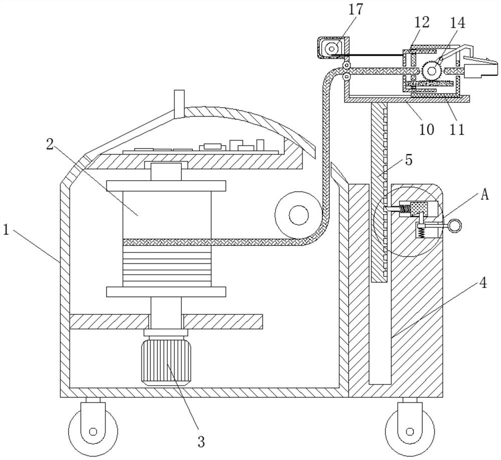
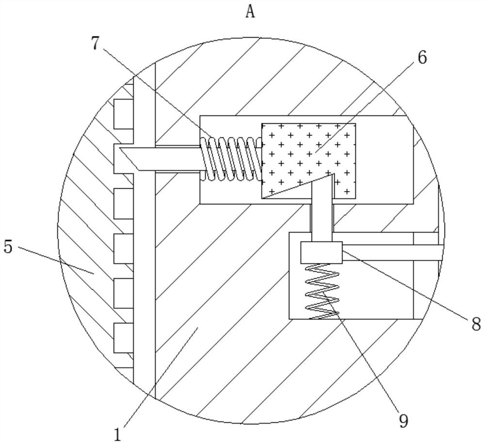
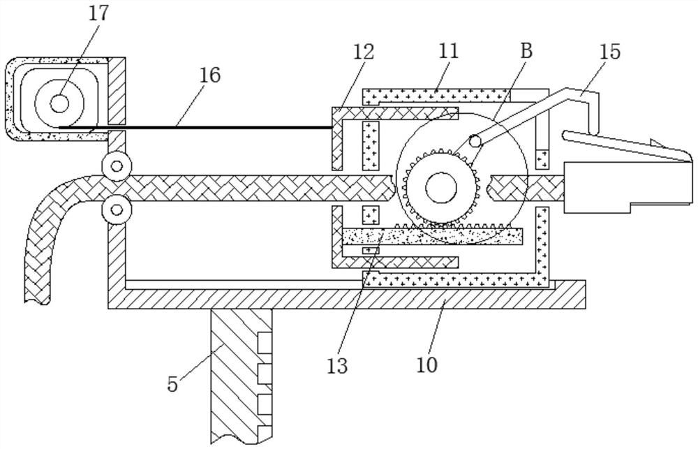
[0026] see Figure 1-4 , a network wiring converging device utilizing the gear rod transmission principle, comprising a wire take-up frame 1, a wire take-up wheel 2, a wire take-up motor 3, a lifting chute 4, a lifting rod 5, a limit pin 6, a limit spring 7, Adjusting block 8, back-moving spring 9, support block 10, slide block 11, slide bar 12, gear bar 13, connecting gear 14, rotating driving lever 15, stay cord 16, pull out motor 17.

[0027] The positions...


PUM


Abstract

The invention relates to the technical field of computer networks, and discloses a network wiring bundling device using the principle of gear rod transmission, comprising a wire take-up frame, and a wire take-up wheel is movably connected inside the wire take-up frame, and the wire take-up wheel is A wire take-up motor is movably connected to the bottom, a lift chute is opened inside the wire take-up frame, a lift rod is slidably connected to the inside of the lift chute, and a limit pin is movably connected to the outside of the lift rod. A limit spring is movably connected to the outside of the pin, an adjustment block is slidably connected to the outside of the limit pin, and a return spring is fixedly connected to the outside of the adjustment block. In order to achieve the effect of bundling the network wiring, avoid when the network wiring is too long, the redundant network wiring is exposed and scattered outside, so as to ensure that the network wiring is clear and neatly stored, which not only facilitates the maintenance and management of the computer, but also ensures the environment. neat and beautiful.

Description

technical field [0001] The invention relates to the technical field of computer networks, in particular to a network connection converging device utilizing the gear bar transmission principle. Background technique [0002] Computer network technology is the product of the combination of communication technology and computer technology. Computer network is a collection of scattered and independent computers connected to each other on the earth according to network protocols. The connection medium can be cables, twisted pairs, optical fibers, microwaves, and carrier waves. Or communication satellites, the computer network has the function of sharing hardware, software and data resources, and has the ability to centrally process, manage and maintain shared data resources, [0003] Because the length of the network connection cable is too long, it is not necessary to use that length. In order to save trouble, the user usually directly nests the network connection cable and place...

Claims


Application Information

Patent Timeline
Patent Type & Authority Patents(China)
IPC IPC(8): H01R13/629H01R13/72
CPCH01R13/629H01R13/72
Inventor 沈金山
Owner 杭州兴长科技有限公司
Learn More