
Method for testing fatigue shear resistance of new and old concrete joint surface

A technology for new and old concrete and new concrete, which is applied in the direction of testing material strength, measuring device, strength characteristics, etc. by applying repetitive force/pulsation force, so as to achieve the effect of convenient and simple production and prolonging fatigue life.

Pending Publication Date: 2020-08-07
SHANDONG TRANSPORTATION INST +1
View PDF5 Cites 1 Cited by
  • Summary
  • Abstract
  • Description
  • Claims
  • Application Information

AI Technical Summary

Problems solved by technology

[0004] The technical task of the present invention is to provide a method for testing the fatigue shear performance of the new-old concrete interface to solve the problem of how to predict the fatigue shear performance of the new-old concrete interface

Method used


Image

  • Method for testing fatigue shear resistance of new and old concrete joint surface
  • Method for testing fatigue shear resistance of new and old concrete joint surface
  • Method for testing fatigue shear resistance of new and old concrete joint surface

Examples


Embodiment 1

[0048] The new and old concrete interface fatigue shear performance test method of the present invention, the method is specifically as follows:

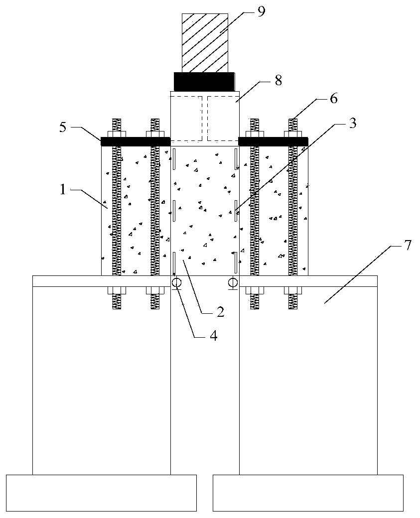
[0049] S1, two prefabricated old concrete test pieces 1 are respectively fixed on two symmetrically placed steel supports 7;

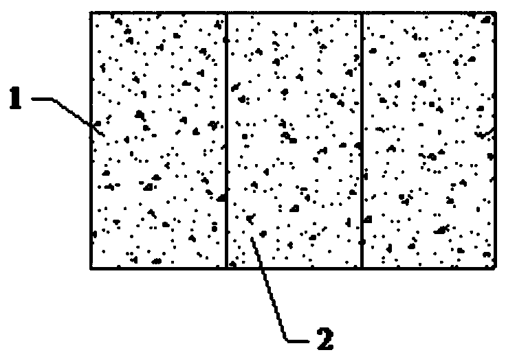
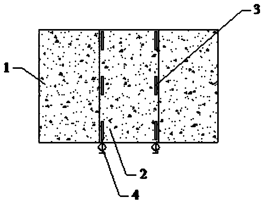
[0050] S2. Pouring new concrete specimen 2 between two old concrete specimens 1, two old concrete specimens 1 and new concrete specimen 2 are used as poured complete test specimens, as attached figure 1 As shown, the new concrete specimen 2 is poured after the old concrete specimen 1 is hoisted and fixed; the length L of the new concrete specimen 2 1 , width L 2 and height L 3 The length, width and height of the old concrete specimen 1 are the same respectively; Carry out chiseling treatment; after chiseling treatment, use a hair dryer to blow off the concrete debris, rinse it with clean water and keep the joint surface moist until pouring new concrete specimen 2. as attached image 3 As shown, a steel ...

Embodiment 2

[0066] Taking an old concrete specimen with a length of 20cm, a width of 40cm, and a height of 50cm as an example, the details are as follows:

[0067] (1), prefabricated old concrete specimen 1, the length, width and height are 20cm, 40cm, and 50cm respectively;

[0068] (2), hoist the old concrete test piece 1 to the steel support 7 and put it in place, and fix the old concrete test piece 1 with the steel backing plate 5 and 4 fixing bolts 6; wherein, the steel backing plate 5 is located on the old concrete test piece 1, the steel support 7 is at the bottom;

[0069] (3) Use a chisel hammer to chisel 2 pieces of old concrete specimen 1 at the joint surface, then use a blower to blow off the residual and loose concrete debris, rinse it with drinking water and keep the joint surface moist, Formwork is erected between two pieces of old concrete, and new concrete specimen 2 is poured to form a test specimen. After the curing is completed, the formwork is removed, and the fabric...


PUM

PropertyMeasurementUnit
Lengthaaaaaaaaaa
Widthaaaaaaaaaa
Heightaaaaaaaaaa

Abstract

The invention discloses a method for testing fatigue shear resistance of a new and old concrete joint surface. The invention belongs to the field of concrete performance detection, aims at solving thetechnical problem of how to predict the fatigue shear resistance of the joint surface of new and old concrete, and adopts the technical scheme that the method specifically comprises the following steps: S1, two prefabricated old concrete test pieces are respectively fixed on two steel supports which are symmetrically arranged; S2, a new concrete test piece is poured between the two old concrete test pieces, and the two old concrete test pieces and the new concrete test piece are poured to form a complete test piece; S3, strain gauges are attached to the joint surfaces formed by the two side surfaces of the new concrete test piece and the side surfaces of the two old concrete test pieces, and dial gauges are arranged on the two sides of the bottom edge of the new concrete test piece; S4, asteel distribution beam is arranged below the MTS loading equipment actuator; S5, a shear ultimate bearing capacity static loading test is performed on the complete test specimen poured in the step S2 to obtain strain and deflection data and shear ultimate bearing capacity Pu; and S6, a new concrete test piece is prefabricated, and a fatigue dynamic loading test is carried out to obtain the fatigue failure loading times Ni.

Description

technical field [0001] The invention relates to the field of concrete performance detection, in particular to a method for testing the fatigue shear performance of a joint surface of old and new concrete. Background technique [0002] Such as long-span bridges, offshore structures, dams and other infrastructures are subject to repeated loads through vehicle traffic or wind and wave loads, and usually these infrastructures require multiple concrete pours to form a whole. The slabs are hoisted in place, and then concrete is poured between the two hollow slabs to combine them into a whole. In large concrete structures involving large volumes of concrete, construction is likewise carried out in several stages, thus creating a interface between old and new concrete. In addition, in many structures that need to be reinforced, it is often necessary to pour concrete, which leads to the formation of joint surfaces between continuous concrete. The joint surface is considered to be o...

Claims


Application Information

Patent Timeline
IPC IPC(8): G01N3/32G01N3/06
CPCG01N3/32G01N3/062G01N2203/0005G01N2203/0025G01N2203/0073
Inventor 李鹏程苏建明周广利徐文博孙玉渠广镇李才孙粉粉郭庆辉
Owner SHANDONG TRANSPORTATION INST
Learn More