
Dehumidification device utilizing photovoltaic power supply and air conditioning system

A photovoltaic power supply and air-conditioning system technology, applied in air-conditioning systems, photovoltaic power generation, circuit devices, etc., can solve problems such as high energy consumption and poor experience in dehumidification methods, and achieve the goals of improving operating efficiency, reducing energy consumption, and enhancing heat exchange effects Effect

Pending Publication Date: 2020-08-07
QINGDAO HAIER AIR CONDITIONER GENERAL CORP LTD +1
View PDF0 Cites 0 Cited by
  • Summary
  • Abstract
  • Description
  • Claims
  • Application Information

AI Technical Summary

Problems solved by technology

[0005] In order to solve at least one of the above-mentioned problems in the prior art, that is, in order to solve the problems of poor experience and high energy consumption in the dehumidification method of the existing air conditioner, the present invention provides a dehumidification device powered by photovoltaics. The dehumidification device includes: dehumidification The dehumidification box is provided with a dehumidification inlet, a dehumidification outlet, a reduction inlet and a reduction outlet, the dehumidification inlet or the dehumidification outlet is provided with a dehumidification fan, and the reduction inlet Or the reduction air outlet is provided with a reduction fan; a solid adsorption component, the solid adsorption component is fixed in the dehumidification box, and the solid adsorption component includes a solid adsorbent; a reduction component, the reduction component includes a reduction coil , the reduction coil is partially coiled on the solid adsorption component, and the heat exchange medium is allowed to flow through the reduction coil; the photovoltaic module, the photovoltaic module is connected with the dehumidification fan and the reduction fan respectively, for Supply power to the dehumidification fan and the reduction fan

Method used


Image

  • Dehumidification device utilizing photovoltaic power supply and air conditioning system
  • Dehumidification device utilizing photovoltaic power supply and air conditioning system
  • Dehumidification device utilizing photovoltaic power supply and air conditioning system

Examples


Embodiment 1

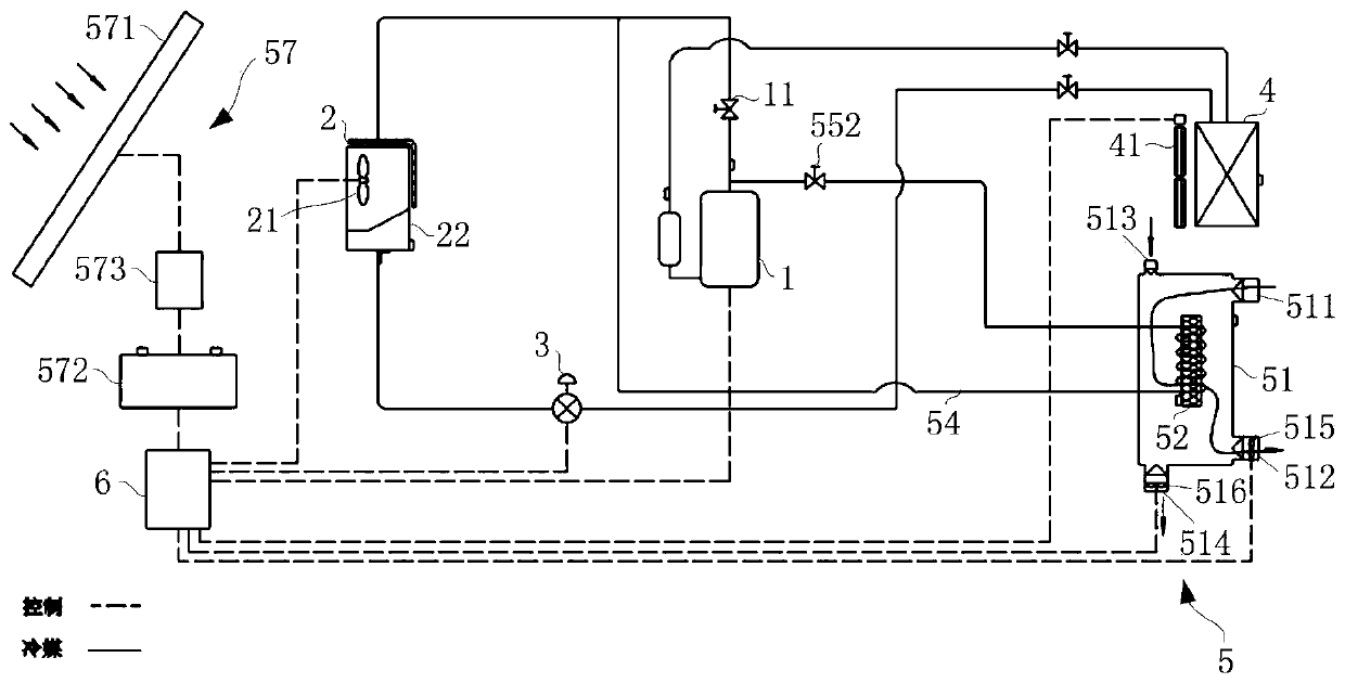
[0037] First refer to figure 1 , describe the air conditioning system of the present invention. in, figure 1 It is a system diagram of the first embodiment of the air conditioning system of the present invention.

[0038] Such as figure 1 As shown, in order to solve the problems of poor dehumidification experience and high energy consumption in existing air conditioners, the air conditioner system of the present application mainly includes a compressor 1, an outdoor heat exchanger 2, an external fan 21, a second throttling element 3, and an indoor heat exchanger. Heater 4, internal fan 41 and master controller 6. The compressor 1, the outdoor heat exchanger 2, the outdoor fan 21, the second throttling element 3 and the general controller 6 are arranged in the cabinet 22 of the outdoor unit, and the indoor heat exchanger 4 and the indoor fan 41 are arranged in the indoor unit. Wherein, the compressor 1 , the outdoor heat exchanger 2 , the second throttling element 3 and the...

Embodiment 2

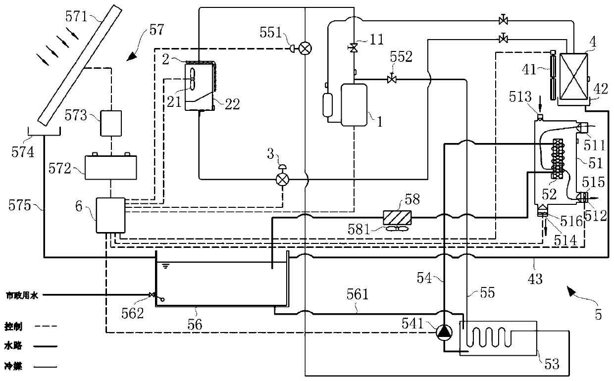
[0046] Refer below figure 2 , to introduce a more preferred implementation manner of the present application. in, figure 2 It is a system diagram of the second embodiment of the air conditioning system of the present invention.

[0047] Such as figure 2 As shown, in a more preferred embodiment, the air conditioning system mainly includes a compressor 1, an outdoor heat exchanger 2, an external fan 21, a second throttling element 3, an indoor heat exchanger 4, an internal fan 41, an indoor connection Water pan 42, condensed water pipe 43 and master controller 6. The compressor 1, the outdoor heat exchanger 2, the external fan 21, the second throttling element 3 and the master controller 6 are arranged in the cabinet 22 of the outdoor unit, and the indoor heat exchanger 4, the indoor fan 41 and the indoor water tray 42 are arranged In the indoor unit, one end of the condensation water pipe 43 communicates with the indoor water receiving tray 42, and the other end leads ou...

Embodiment 3

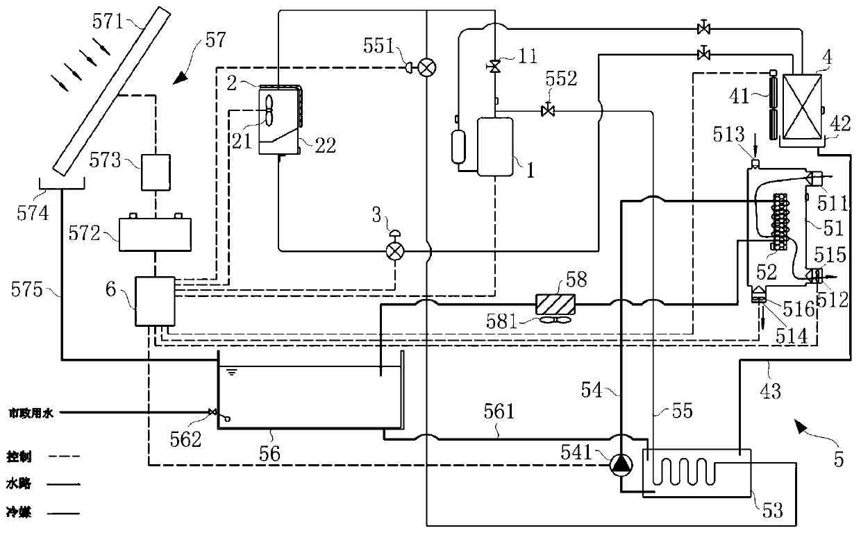
[0075] Combine below image 3 , to introduce another alternative implementation manner of the present invention. in, image 3 It is a system diagram of the third embodiment of the air conditioning system of the present invention.

[0076] Such as image 3 As shown, the difference between this embodiment and Embodiment 2 is that the condensed water pipe 43 is led out of the outdoor and communicates with the reduced water tank 53 . This setting method can improve the heat exchange effect between the refrigerant in the reduction water tank 53 and the heat exchange liquid, improve the operating efficiency of the air conditioning system, and reduce the energy consumption of the system.

[0077] Similarly, the water collecting pipe 575 can also be directly connected with the reduced water tank 53 , so that the collected rainwater can be directly used to replenish water for the reduced water tank 53 to cool down.


PUM


Abstract

The invention relates to the technical field of air conditioning, in particular to a dehumidification device utilizing photovoltaic power supply and an air conditioning system, and aims at solving theproblems that an existing dehumidification method for the air conditioner is poor in experience and high in energy consumption. In order to achieve the purpose, the dehumidification device comprisesa dehumidification box, a reduction assembly and a photovoltaic module, the solid adsorption assembly is fixedly arranged in the dehumidification box; the reduction assembly comprises a reduction coilpipe, part of the reduction coil pipe is arranged on the solid adsorption assembly in a coiled mode, a heat exchange medium is allowed to flow through the reduction coil pipe; and the photovoltaic module is respectively connected with the dehumidification fan and the reduction fan. The indoor temperature and humidity can be independently adjusted, power consumption is reduced, and energy is saved.

Description

technical field [0001] The invention relates to the technical field of air conditioning, in particular to a dehumidification device and an air conditioning system powered by photovoltaics. Background technique [0002] With the rapid development of my country's economy and the continuous improvement of the quality of life, the popularity of air conditioners is also increasing. When people use the air conditioner, in addition to using the air conditioner to adjust the indoor temperature, they pay more and more attention to the adjustment of the indoor humidity. [0003] However, traditional air conditioners mostly use refrigeration mode to adjust humidity, that is, use low-temperature refrigerant with a temperature lower than the dew point of the air to exchange heat with indoor air, so that the moisture in the air is condensed into a liquid state and then discharged. However, the above dehumidification method will not only lead to a sudden drop in the indoor temperature and...

Claims


Application Information

Patent Timeline
IPC IPC(8): F24F1/0083H02J7/35
CPCF24F1/0083H02J7/35Y02E10/56
Inventor 罗荣邦王飞董旭许文明张心怡
Owner QINGDAO HAIER AIR CONDITIONER GENERAL CORP LTD
Learn More