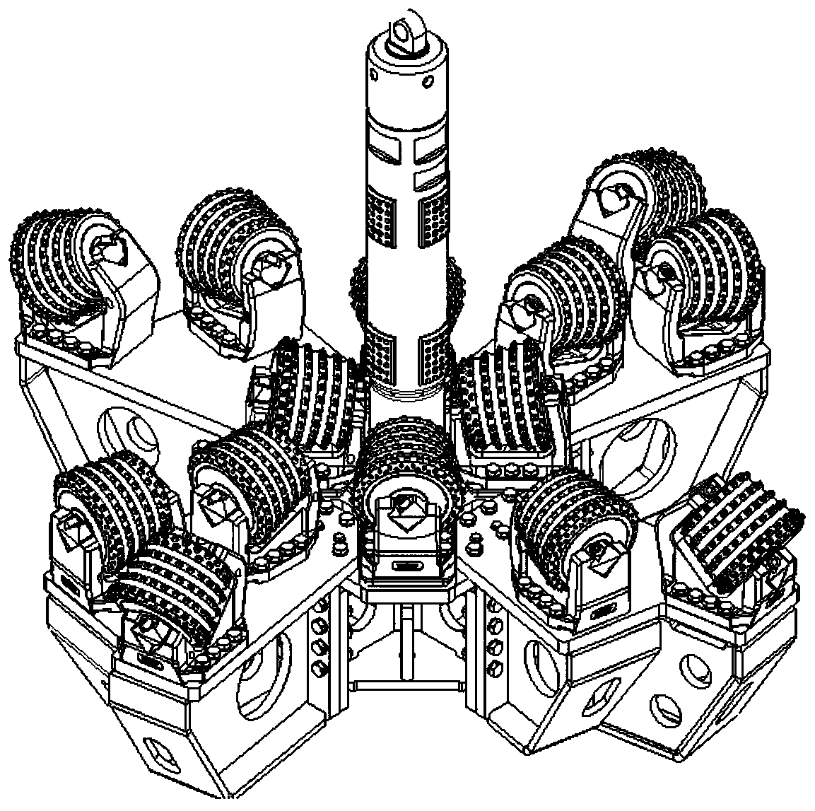
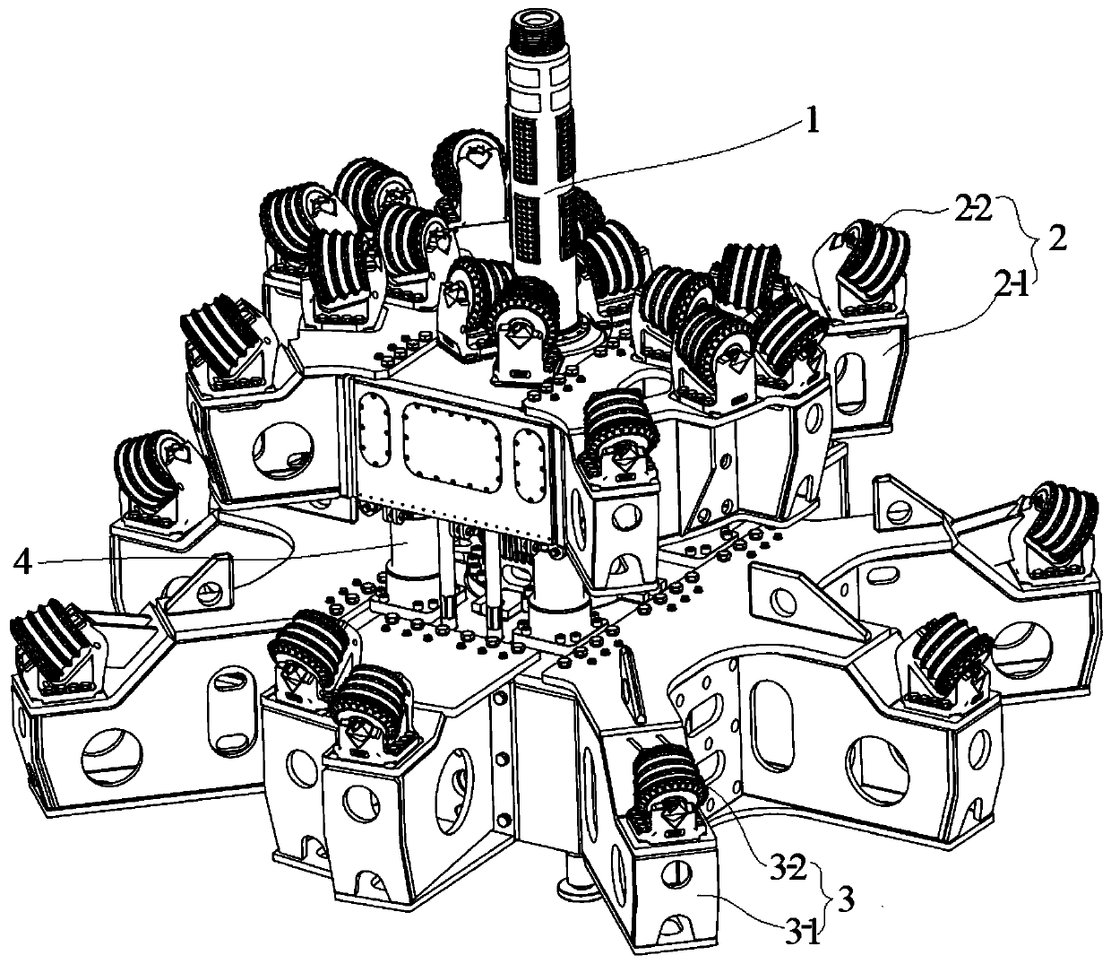
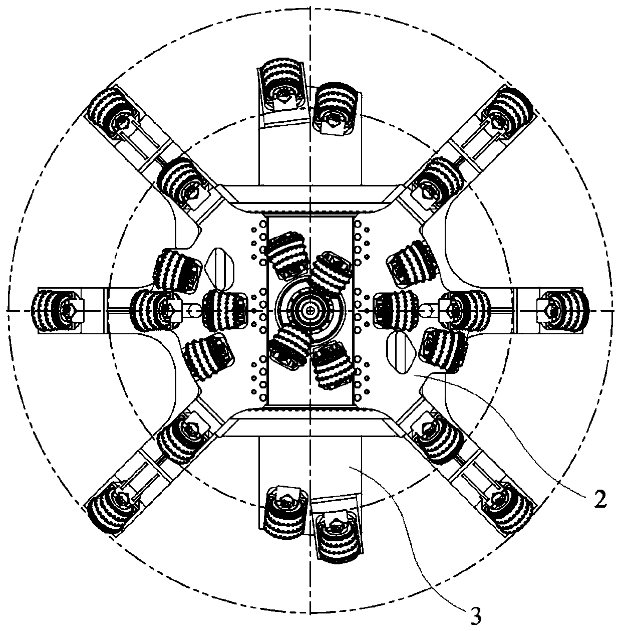
Compound reaming cutter head and control method thereof

A technology of cutter head and control valve, applied in the field of mining machinery, can solve problems such as troublesome disassembly and assembly, time-consuming and laborious, and achieve the effect of shortening construction time, avoiding potential safety hazards and saving labor intensity.

Active Publication Date: 2020-08-07
HUNAN CHUANGYUAN HIGH TECH MACHINERY CO LTD
View PDF7 Cites 0 Cited by
  • Summary
  • Abstract
  • Description
  • Claims
  • Application Information

AI Technical Summary

Problems solved by technology

[0006] The main purpose of the present invention is to provide a reaming cutter head and its control method, aiming at solving the problem that the existing reaming cutter head needs to be constructed twice from the bottom to the top when reaming large-diameter holes, which makes disassembly and assembly troublesome, time-consuming and labor-intensive. question

Method used


Image

  • Compound reaming cutter head and control method thereof
  • Compound reaming cutter head and control method thereof
  • Compound reaming cutter head and control method thereof

Examples


Embodiment Construction

[0038] The following will clearly and completely describe the technical solutions in the embodiments of the present invention with reference to the accompanying drawings in the embodiments of the present invention. Obviously, the described embodiments are only part of the embodiments of the present invention, not all of them. Based on the embodiments of the present invention, all other embodiments obtained by persons of ordinary skill in the art without creative efforts fall within the protection scope of the present invention.

[0039] It should be noted that all directional indications (such as up, down, left, right, front, back...) in the embodiments of the present invention are only used to explain the relationship between the components in a certain posture (as shown in the accompanying drawings). Relative positional relationship, movement conditions, etc., if the specific posture changes, the directional indication will also change accordingly.

[0040] In addition, in t...


PUM


Abstract

The invention discloses a compound reaming cutter head and a control method thereof. The compound reaming cutter head comprises a pull rod, an upper cutter head, a lower cutter head and a plunger oilcylinder, wherein the pull rod is arranged at the center of the upper cutter head and the lower cutter head in a penetrating mode, and the diameter of the lower cutter head is larger than that of theupper cutter head; the lower cutter head is fixedly connected with the bottom end of the pull rod; the plunger oil cylinder comprises a cylinder barrel and a piston rod, the cylinder barrel is fixed to the top end of the lower cutter head, and the piston rod can extend upwards; and the upper cutter head is located above the plunger oil cylinder and makes contact with the piston rod, and the uppercutter head is circumferentially fixed to the pull rod and can slide up and down relative to the pull rod. By the compound reaming cutter head, one-time upward reaming well forming can be realized.

Description

technical field [0001] The invention belongs to the technical field of mining machinery, and in particular relates to a compound expansion cutter head and a control method thereof. Background technique [0002] Raise drilling rigs use hobs on the cutter head to break rocks for hole reaming. The hole reaming process of the traditional raise drilling rig is usually: after the pilot hole is completed, install the reaming cutterhead on the lower part, and use the reaming cutterhead to complete the hole reaming at one time. The drillable diameter of the traditional reaming cutterhead is within 1500mm . [0003] The diameter of the new raise drilling rig is 3500mm at one time, which is limited by the maximum output capacity of the power head. If you want to construct a raise with a diameter larger than 3500mm, you need to ream the hole twice from the bottom to the top to complete: 1. After the pilot hole is completed, first Install a small cutterhead at the bottom and construct ...

Claims


Application Information

Patent Timeline
Patent Type & Authority Applications(China)
IPC IPC(8): E21D3/00
CPCE21D3/00
Inventor 王毅唐安平未崴熊钰明谭崎文
Owner HUNAN CHUANGYUAN HIGH TECH MACHINERY CO LTD
Why Eureka
Try Eureka