Eureka AIR delivers breakthrough ideas for toughest innovation challenges, trusted by R&D personnel around the world.

Composite temporary water retaining structure and construction method combining trd construction method diaphragm wall and earth-rock cofferdam

A technology of earth-rock cofferdam and water-retaining structure, which is applied in the direction of basic structure engineering, dams, sheet pile walls, etc., can solve the problems of high construction cost, great influence of steel price, and difficult quality assurance, so as to reduce the difficulty of demolition, prevent The advantage of seepage effect and the effect of improving the water blocking effect

Active Publication Date: 2021-11-05
POWERCHINA HUADONG ENG COPORATION LTD
View PDF2 Cites 1 Cited by
  • Summary
  • Abstract
  • Description
  • Claims
  • Application Information

AI Technical Summary

Problems solved by technology

Among them, the earth-rock cofferdam can only solve the upper water retaining problem; the construction efficiency of the masonry cofferdam is low, the cost is high, and a dry working environment must be created during its own construction; the quality of the underwater pouring method of the concrete cofferdam is difficult to guarantee, and the cost is relatively high High and difficult to dismantle, it is generally used for permanent water retaining structures. At the same time, concrete cofferdams generally need to act on bedrock, which is not suitable for environments with a lot of silt such as rivers or lakes; the uniformity of steel sheet pile cofferdams to the stratum The requirements are relatively high. When the stratum changes, it will directly affect the verticality control of the steel plate construction. The adaptability to the crushed and pebble stratum is weak, and the steel plate may not be able to be beaten, and the steel price is greatly affected by the market.

Method used


Image

  • Composite temporary water retaining structure and construction method combining trd construction method diaphragm wall and earth-rock cofferdam

Examples


Embodiment Construction

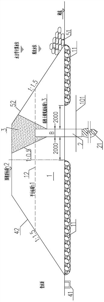
[0021] Refer to attached picture. The composite temporary water-retaining structure combined with the TRD construction method diaphragm wall and the earth-rock cofferdam provided by the present invention is composed of an earth-rock cofferdam 1, a TRD construction method diaphragm wall 2, and a cohesive soil filling area 3, and the TRD construction method diaphragm wall 2 is configured in The earth-rock cofferdam 1 is biased toward the upstream side. Concrete construction process of the present invention is as follows:

[0022] (1) Before the construction of the earth-rock cofferdam, remove the floating mud (0.5m thick) within the range of the weir foundation to ensure that the cofferdam is in contact with the river bed. In some areas, it is necessary to further stabilize the weir foundation by riprapping the silt. The reference number 11 is Rock riprap area (thickness 0.5m). The overall inclination angle of the contact surface should not be greater than 2°. In order to avo...


PUM


Abstract

The invention provides a composite temporary water-retaining structure combined with a TRD construction method diaphragm wall and an earth-rock cofferdam and a construction method, which is composed of an earth-rock cofferdam, a TRD construction method diaphragm wall, and a cohesive soil filling area. The present invention establishes an earth-rock cofferdam as the basic structure, adopts the internal TRD continuous wall as the core wall, and assists in backfilling cohesive soil at the top, and performing curtain grouting at the bottom depending on the stratum to form a combined water retaining system above the bottom of the river (lake). Solving the problem of water blocking above the elevation of the river (lake) bottom and anti-seepage below the elevation of the river (lake) bottom not only improves the water blocking effect of temporary construction facilities, but also reduces the difficulty of demolition and achieves the effect of saving investment. Cross-river, cross-lake and other water surface elevations provide a feasible solution for the design and implementation of water-retaining structures using open-cut construction conditions. Compared with other cofferdam structures, the entire temporary water retaining structure has advantages in terms of construction period, investment, and anti-seepage effect.

Description

technical field [0001] The invention relates to a composite temporary water-retaining structure combined with an earth-rock cofferdam and a construction method of a TRD continuous wall (TRD, Trench cutting Re-mixing Deep wall, constant thickness cement-soil continuous mixing wall), which is suitable for such as crossing rivers, The field of temporary water retaining design for a class of engineering construction below the water surface elevation such as across the lake using open cut construction. Background technique [0002] Generally, tunnels, box culverts, pipelines and comprehensive pipe gallery projects below water surface elevations such as crossing rivers and lakes need to be constructed with open cut construction in the construction section to ensure the safety of personnel and machinery in the foundation pit. Dry working environment and construction safety. The anti-seepage of foundation pit is one of the key difficulties in this type of project. It is necessary t...

Claims


Application Information

Patent Timeline
Patent Type & Authority Patents(China)
IPC IPC(8): E02B7/04E02D5/18E02D19/04
CPCE02B7/04E02D5/18E02D19/04
Inventor 邓磊邓漓周平刘一宏张志鹏姚琦刘岭楠颜锦凯王晗
Owner POWERCHINA HUADONG ENG COPORATION LTD
Why Eureka
Eureka Blog
Learn More