Portable washing machine
A portable washing machine and laundry ball technology, applied in the field of washing machines, can solve the problems of high price, large volume and weight, occupying space, etc., and achieve the effects of low price, small size and weight, and easy portability
- Summary
- Abstract
- Description
- Claims
- Application Information
AI Technical Summary
Problems solved by technology
Method used
Image
Examples
Embodiment 1
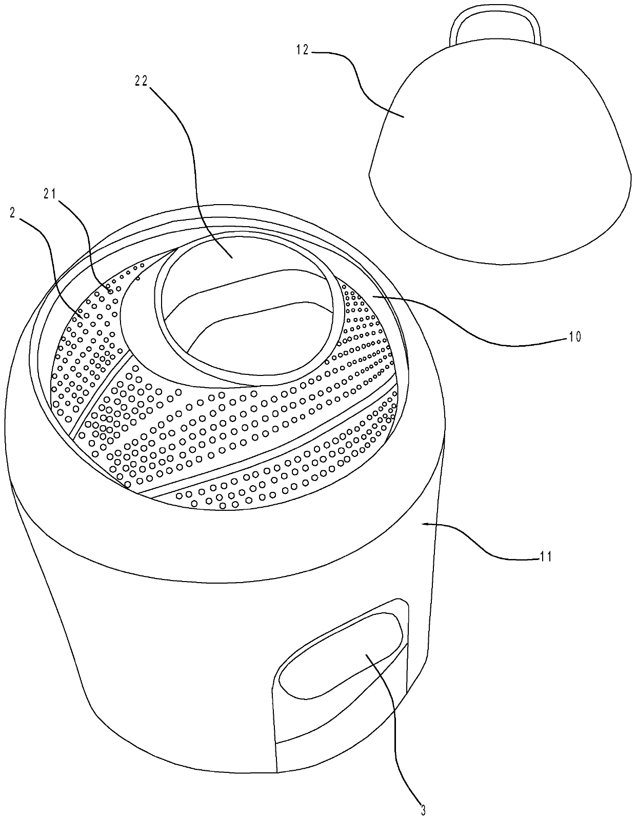
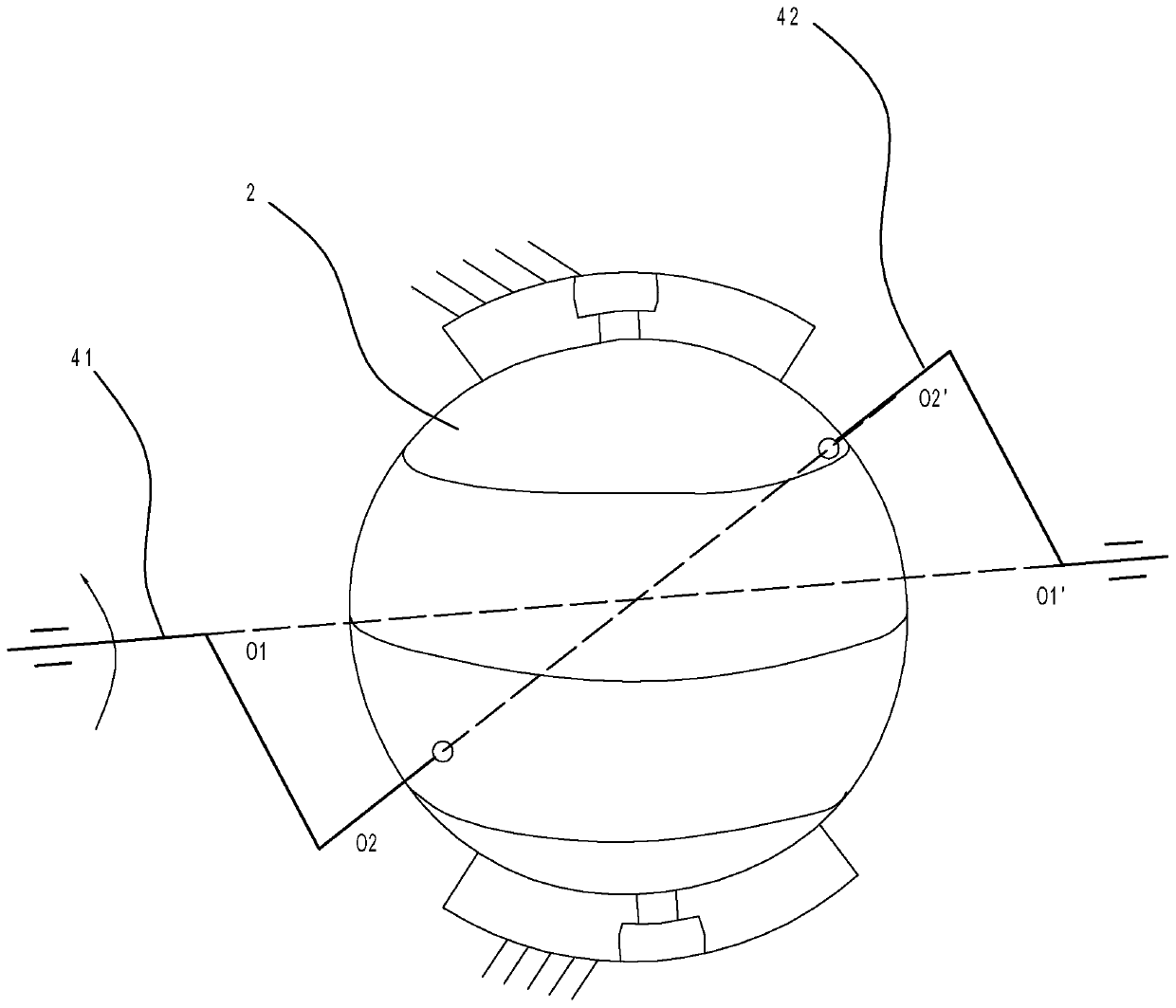
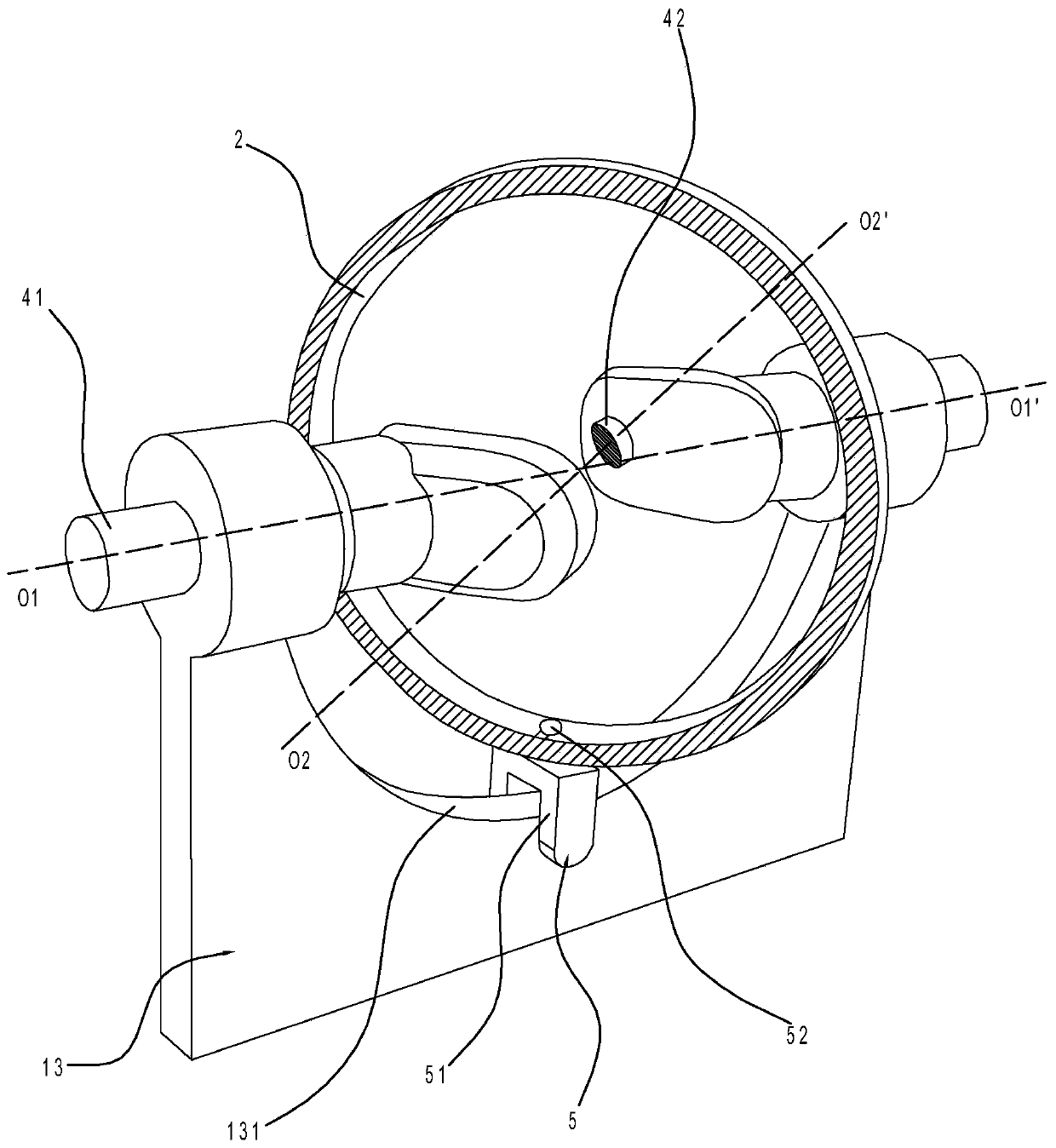
[0025] Such as Figures 1 to 4 As shown, the present invention provides a portable washing machine, including a casing 11, a cover 12, a washing ball 2, a ball cover 22, a first rotating shaft 41, a second rotating shaft 42, a guide mechanism and a driving mechanism.
[0026] Wherein, a washing chamber 10 opening outwards is formed in the casing 11, and the cover 12 covers the opening of the washing chamber 10. A drain pipe is connected to the bottom of the washing chamber 10, and a drain switch is arranged on the drain pipe. A base 13 is provided at the bottom of the cavity 10, and a sealed laundry ball 2 is arranged in the laundry cavity 10. A ball cover 22 is screwed on the laundry ball 2. A filter hole 21 is provided on the outer wall of the laundry ball 2. The base 13 rotates A set of oppositely arranged first rotating shafts 41 is provided, the axes of the two first rotating shafts 41 are on the same straight line passing through the center of the laundry ball 2, one of ...
Embodiment 2
[0033] Please combine Figure 5 As shown, the difference between Embodiment 2 and Embodiment 1 is that, in this embodiment, the guide mechanism includes an arc-shaped chute 132 arranged on the base 13 and below the laundry ball 2, and in the arc-shaped chute 132 is slidingly provided with a sliding body 53, and the top of the sliding body 53 is connected with the outer wall at the bottom of the laundry ball 2. Further, the sliding body 53 is a cylinder or a sphere. In Embodiment 1, the top end of the guide column portion 52 on the guide member is rotatably arranged on the outer wall of the bottom of the laundry ball 2, while in Embodiment 2, the top of the sliding body 53 is fixed on the bottom outer wall of the laundry ball 2, And the sliding body 53 can rotate in the arc chute 132 .
Embodiment 3
[0035] Please combine Figure 6As shown, the difference between Embodiment 3 and Embodiment 1 is that, in this embodiment, the driving mechanism is driven manually. 32. The bottom of the pedal 3 is provided with a pedal spring 33, the middle part of the curved rod 31 is hinged to the bottom of the casing 11, one end of the curved rod 31 is connected with the pedal 3, and the other end of the curved rod 31 is connected with an arc-shaped rack 311, driving the gear 32 is sheathed on one of the first rotating shafts 41, and the arc-shaped rack 311 meshes with the driving gear 32.
[0036] Alternatively, a manual driving method is adopted. At this time, the driving mechanism includes a hand crank, which is rotatably arranged on the outer wall of the casing 11 , and the hand crank is connected to one of the first rotating shafts 41 .
PUM
 Abstract
Description
Claims
Application Information
 - R&D
- Intellectual Property
- Life Sciences
- Materials
- Tech Scout
- Unparalleled Data Quality
- Higher Quality Content
- 60% Fewer Hallucinations
Browse by: Latest US Patents, China's latest patents, Technical Efficacy Thesaurus, Application Domain, Technology Topic, Popular Technical Reports.
© 2025 PatSnap. All rights reserved.Legal|Privacy policy|Modern Slavery Act Transparency Statement|Sitemap|About US| Contact US: help@patsnap.com


