Oil-containing waste pyrolysis equipment and reduction treatment method

A waste and pyrolysis technology, which is used in the treatment of hydrocarbon oil, the preparation of liquid hydrocarbon mixtures, and the petroleum industry. It can solve the problems of leakage at the end of the drive shaft, coking of the spiral wall, affecting heat transfer, etc., so as to prevent injury to personnel and equipment. , Avoid coking to affect heat transfer and improve thermal efficiency

Pending Publication Date: 2020-08-07
东营兴盛环保科技股份有限公司
View PDF0 Cites 1 Cited by
  • Summary
  • Abstract
  • Description
  • Claims
  • Application Information

AI Technical Summary

Problems solved by technology

[0003] However, the tank rotation method uses the entire tank of the equipment to rotate. After high-temperature heating and wear, it is easy to cause leakage of the drive shaft end, and leakage of the shaft ends on both sides will easily form air circulation channels, causing the oxygen content in the tank to exceed the standard and cause an explosion; In the pyrolysis equipment used by the spiral propulsion method, when the material enters the process, it is easy to cause debris to wrap around the shaft and the spiral wall to coke, which affects heat transfer, and it is impossible to install an explosion-proof pressure relief device, which makes it difficult to deal with oily waste and plastic cloth.

Method used


Image

  • Oil-containing waste pyrolysis equipment and reduction treatment method

Examples


Embodiment Construction

[0038] The following will clearly and completely describe the technical solutions in the embodiments of the present invention with reference to the accompanying drawings in the embodiments of the present invention. Obviously, the described embodiments are only some, not all, embodiments of the present invention. Based on the embodiments of the present invention, all other embodiments obtained by persons of ordinary skill in the art without making creative efforts belong to the protection scope of the present invention.

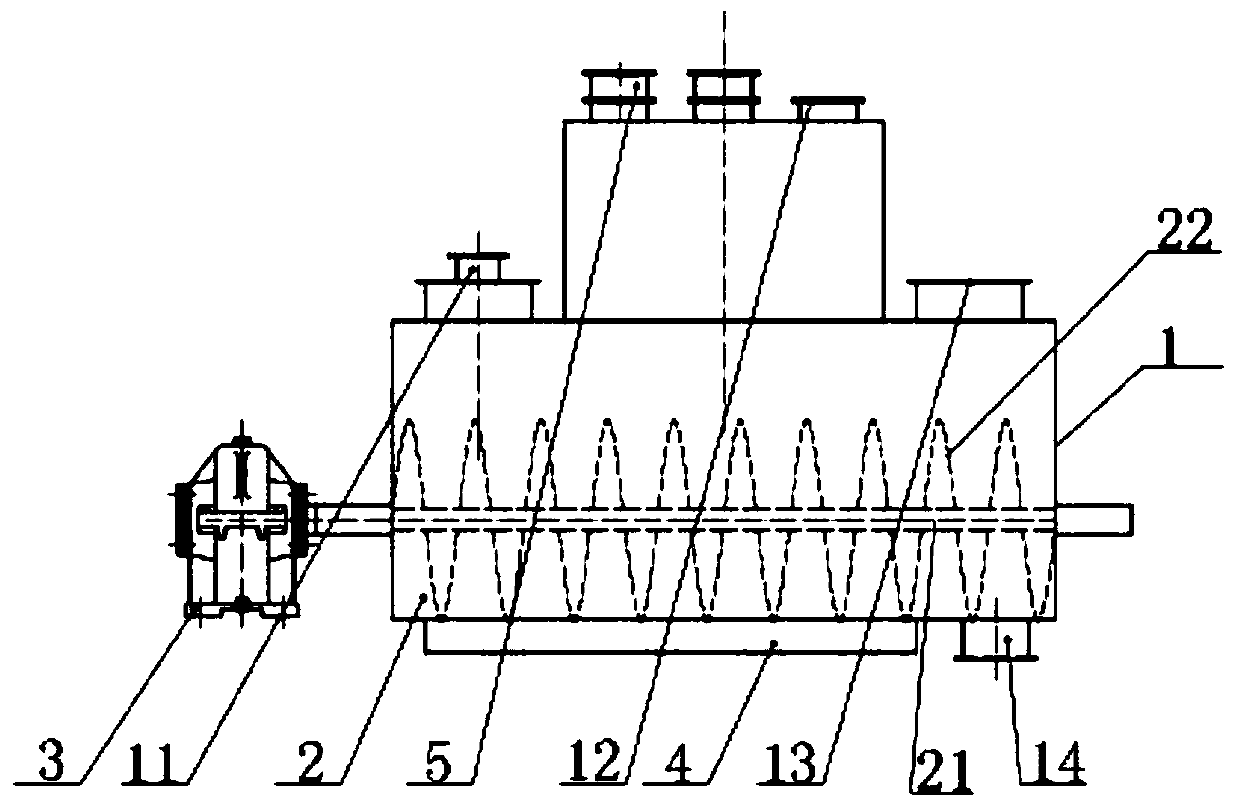
[0039] Such as figure 1 As shown, the embodiment of the present invention discloses a kind of oily waste pyrolysis equipment, including a sealed tank body 1, a stirring and scraping device 2, a power drive device 3, a heating device 4, a condenser and an oil-water separation device, and the sealed tank body 1 The top has a feed port 11, an air outlet 12 and an observation window 13, and the bottom of the sealed tank 1 has a slag outlet 14; the stirring and scr...


PUM


Abstract

The present invention discloses oil-containing waste pyrolysis equipment and a reduction treatment method. The oil-containing waste pyrolysis equipment comprises a sealed tank body, a stirring and scraping device, a power supply driving device, a heating device, a condenser and an oil-water separation device, the top of the sealed tank body is provided with a feeding opening, an air outlet and anobservation window, and the bottom of the sealed tank body is provided with a slag outlet; the stirring and scraping device is mounted in the sealed tank body; the power supply driving device is fixedoutside the sealed tank body and is in transmission connection with the stirring and scraping device; the heating device is arranged at the periphery of the sealed tank body; the condenser is communicated with the air outlet; and the oil-water separation device is connected and communicated with the condenser. In the whole process, the tank body is fixed and static, oil-containing waste is stirred through the stirring and scraping device inside the tank body, slag on the inner wall of the tank body is scraped off to prevent coking, leakage is not likely to happen, the safety performance is high, materials cannot coke on the tank wall to influence heat transfer, and pyrolysis is sufficient.

Description

technical field [0001] The invention relates to the technical field of oily waste treatment equipment, and more specifically relates to a pyrolysis equipment and a reduction treatment method for oily waste. Background technique [0002] Pollutants such as oily waste belong to the national hazardous waste, and the environmental management requirements are strict. At present, the treatment methods of oily waste are mainly the tank rotation method and the double-screw propulsion method. [0003] However, the tank rotation method uses the entire tank of the equipment to rotate. After high-temperature heating and wear, it is easy to cause leakage of the drive shaft end, and leakage of the shaft ends on both sides will easily form air circulation channels, causing the oxygen content in the tank to exceed the standard and cause an explosion; In the pyrolysis equipment used by the spiral propulsion method, when the material enters the process, it is easy to cause debris to wrap aro...

Claims


Application Information

Patent Timeline
Patent Type & Authority Applications(China)
IPC IPC(8): C10B53/00C10B47/34C10G1/00
CPCC10B47/34C10B53/00C10G1/002C10G2300/1003
Inventor 王其新刘孟王其雨
Owner 东营兴盛环保科技股份有限公司
Why Eureka
Try Eureka