Plug locking mechanism of transfer box
A technology of locking mechanism and transfer box, which is applied in the direction of transportation and packaging, rigid containers, bottle/can parts, etc., and can solve problems such as difficult positioning of plugs
- Summary
- Abstract
- Description
- Claims
- Application Information
AI Technical Summary
Problems solved by technology
Method used
Image
Examples
Embodiment 1
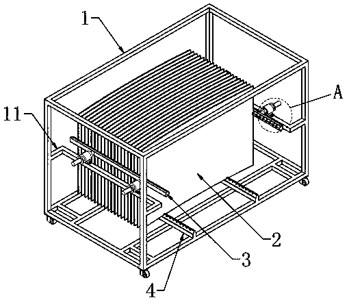
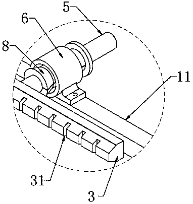
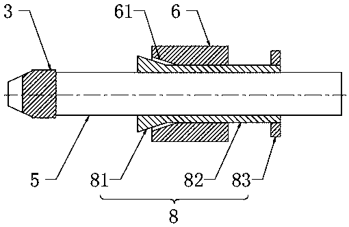
[0039] see Figure 1-3 , the present invention provides a plug locking mechanism for a transfer box, including a push rod 5 and a sleeve 6, the sleeve 6 is arranged on the transfer box 1, and the push rod 5 is slidably sleeved in the sleeve 6, One end of the push rod 5 is connected with the plug 3 . The locking mechanism also includes a locking sleeve 8, which includes a tapered sleeve portion 81, a shaft sleeve portion 82 and a limiting portion 83 connected in sequence from left to right; the shaft sleeve portion 82 is slidable The method is arranged between the outer periphery of the push rod 5 and the inner wall of the sleeve 6; the taper sleeve part 81 is located on the side of the shaft sleeve part 82 close to the plug 3, and at least one expansion joint 811 is opened on the outer periphery of the taper sleeve part 81. Preferably, three expansion joints 811 are evenly distributed on the outer periphery of the tapered sleeve portion 81 , so that the tapered sleeve portion...
Embodiment 2
[0042] see Figure 4-6The outer circumference of the sleeve portion 82 is provided with a first groove 821; the non-return mechanism 9 includes a non-return claw 91 and a first spring 92, one end of the non-return claw 91 is hinged to the side wall of the first groove 821, One end of the first spring 92 is connected to the bottom of the first groove 821, and the other end of the first spring 92 is connected to the side of the non-return claw 91 close to the first groove 821. The first spring 92 is used to make the stop The back claw 91 extends to the outside of the sleeve portion 82 . When the lock sleeve 8 does not hold the push rod 5 tightly, the left end of the non-return claw 91 is squeezed by the inner wall of the sleeve 6 and accommodated in the first groove 821. At this time, the first spring 92 is in a compressed state. When the lock is pulled to the right When the sleeve 8 is tightened, the anti-return pawl 91 also moves to the right relative to the sleeve 6 until th...
Embodiment 3
[0045] see Figure 7-10 , the sleeve 6 is provided with a second through hole 64 . The non-return mechanism 9 includes a non-return cylinder 93 , a non-return rod 94 , a locking cap 95 and a second spring 96 . The non-return cylinder 93 is slidably connected to the second through hole 64 , specifically, the non-return cylinder 93 may be threadedly connected to the second through hole 64 . The non-return rod 94, the lock cap 95 and the second spring 96 are all arranged in the non-return cylinder 93, and the end of the non-return cylinder 93 close to the sleeve part 82 has a non-return hole 931, and the non-return rod 94 is arranged in the The non-return cylinder 93 is close to the end of the shaft sleeve 82 and extends outward from the non-return hole 931. The lock cap 95 is connected to the end of the non-return cylinder 93 away from the shaft sleeve 82. The second spring 96 is clamped on the lock cap. 95 and the non-return rod 94, so that the non-return rod 94 is accommodat...
PUM
 Abstract
Description
Claims
Application Information
 - R&D
- Intellectual Property
- Life Sciences
- Materials
- Tech Scout
- Unparalleled Data Quality
- Higher Quality Content
- 60% Fewer Hallucinations
Browse by: Latest US Patents, China's latest patents, Technical Efficacy Thesaurus, Application Domain, Technology Topic, Popular Technical Reports.
© 2025 PatSnap. All rights reserved.Legal|Privacy policy|Modern Slavery Act Transparency Statement|Sitemap|About US| Contact US: help@patsnap.com


