
Mounting method of energy-saving stator

An installation method and stator technology, applied in ships and other directions, can solve problems such as difficulty in selecting a suitable reference datum for fin segmentation, difficulty in controlling inclination angle and dimensional accuracy, complex line shape of stern column castings, etc., to shorten the overall cycle , solve the difficulty and accuracy, and improve the effect of safety guarantee factor

Active Publication Date: 2020-08-07
中船澄西扬州船舶有限公司
View PDF27 Cites 5 Cited by
  • Summary
  • Abstract
  • Description
  • Claims
  • Application Information

AI Technical Summary

Problems solved by technology

This method has the following defects: due to the complex line shape of the stern column casting, it is extremely difficult to select a suitable reference datum for the installation of each fixed fin segment, and it is difficult to control the inclination angle and dimensional accuracy
Although the above-mentioned document discloses that the front stator blades of the front stator are fixed on a solid non-rotating shaft, and the outer ends of the front stator blades are locked and connected to the conduit by fasteners, they do not disclose the front stator blades. How the leaves are attached to the hub

Method used


Image

  • Mounting method of energy-saving stator
  • Mounting method of energy-saving stator
  • Mounting method of energy-saving stator

Examples


Embodiment Construction

[0045] Below in conjunction with specific embodiment, further illustrate the present invention, it should be understood that these embodiments are only used to illustrate the present invention and are not intended to limit the scope of the present invention, after reading the present invention, those skilled in the art will understand the various equivalent forms of the present invention All modifications fall within the scope defined by the appended claims of the present application.

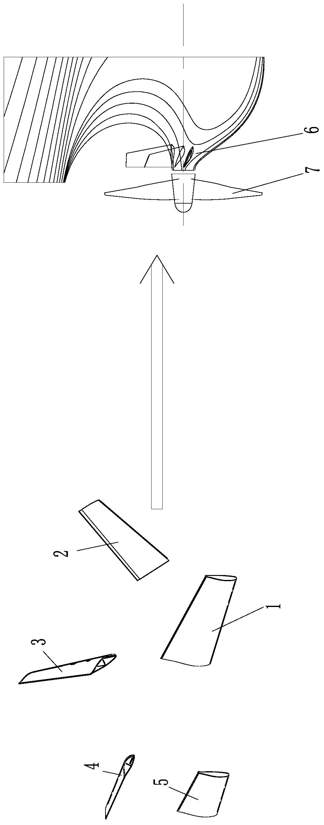
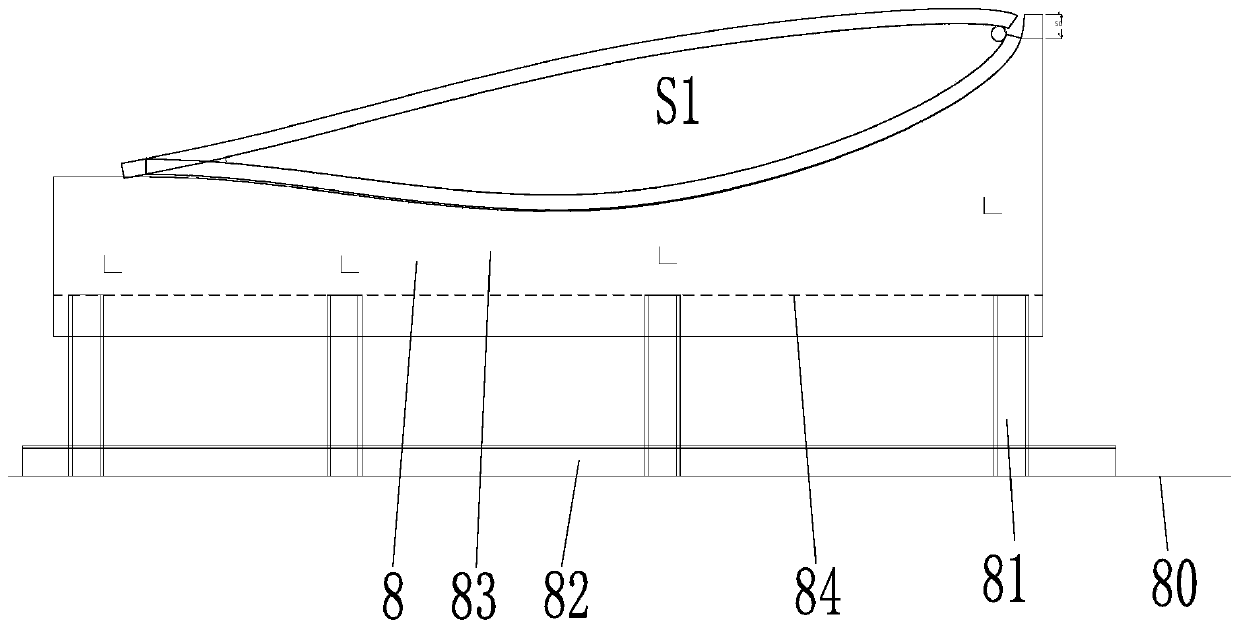
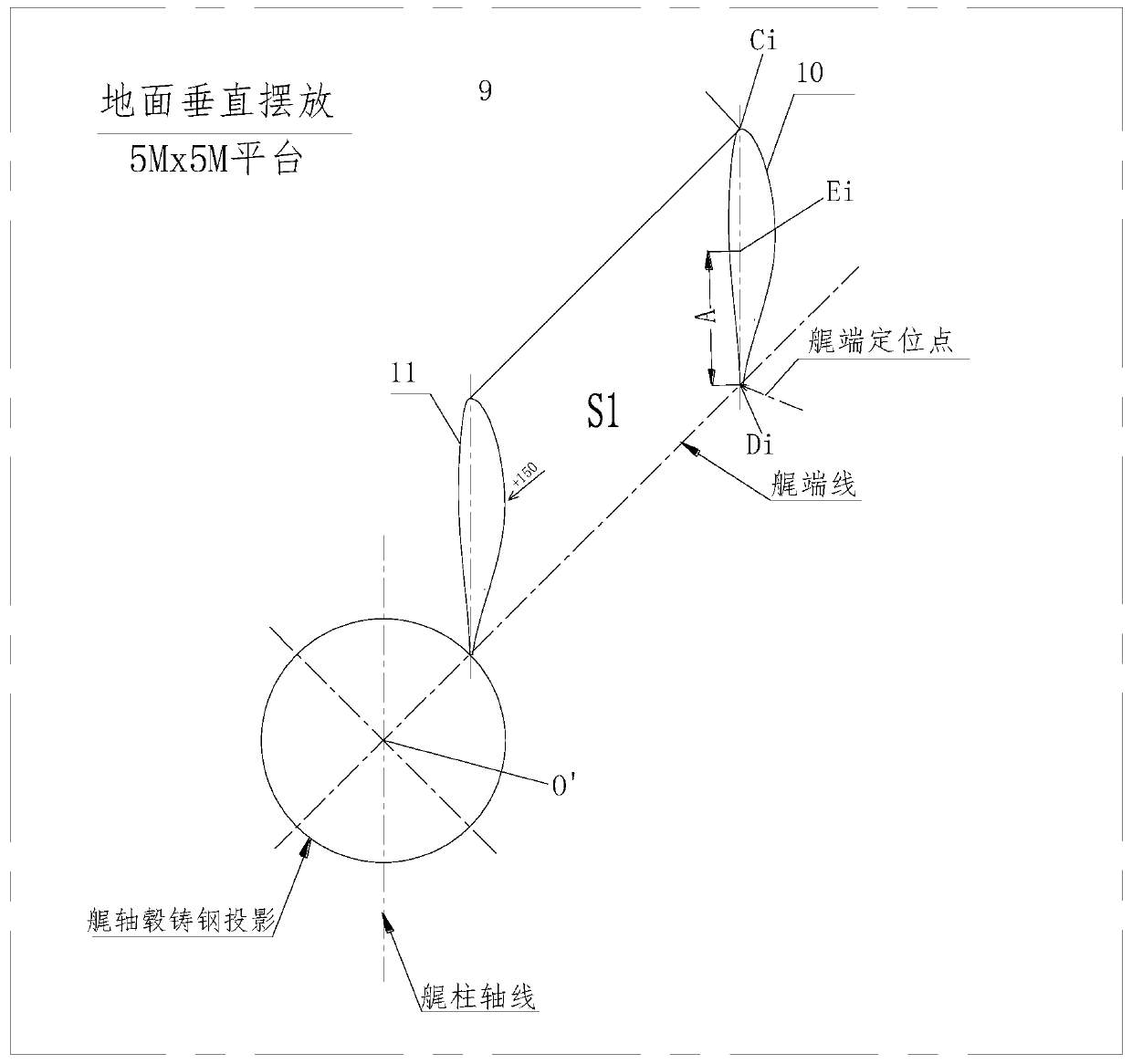
[0046] Such as Figure 2-7 As shown, the energy-saving stator includes a first fixed fin S1, a second fixed fin S2, a third fixed fin S3, a fourth fixed fin P1, and a fifth fixed fin P2.

[0047] On the known design drawings, turn the tail shaft hub upside down, adjust the tail shaft hub to a horizontal state, determine the origin O(0,0,0), and the origin is located on the center point of the projection surface of the tail shaft hub.

[0048] In the vertical state of the fixed fin, calculate t...


PUM


Abstract

The invention belongs to the technical field of ships, and relates to a mounting method of an energy-saving stator, which comprises the following steps of: (1) manufacturing fixed fins in a fragmentation manner, and reserving allowance on the folding end surface of each fixed fin; (2) inverting the tail shaft hub steel casting on a platform, and adjusting the tail shaft hub steel casting to a horizontal state; (3) adjusting the inclination angle and size of the manufactured fixed fin by using a total station and a plumb bob tool, and carrying out OTS pre-closure on the stator; (4) surveying and cutting the allowance of the closed end surface of the fixed fin in place by using a projection method; (5) resetting the trimmed fixed fins and the trimmed tail shaft hub steel casting again according to design requirements, fixing the inclination angles and the space positions of the fixed fins, wherein the adjacent fixed fins are in rigid connection through connecting pieces, and the fixed fins form a stator set; and (6) hoisting the stator group to the inverted tail shaft hub steel casting, and assembling the stator group and the tail shaft hub steel casting. The manufacturing and mounting precision is high, and the manufacturing and mounting period is effectively shortened.

Description

technical field [0001] The invention belongs to the technical field of ships, and in particular relates to an installation method of an energy-saving stator. Background technique [0002] Such as figure 1 As shown, a group of fixed blades 1-5 (i.e. the front stator) propulsion device is installed on the tail shaft hub 6 in front of the marine propeller 7, and the fixed blades 1-5 are installed on the tail shaft hub 6, and the fixed blades 1-5 and The combined device of propeller 7 is the energy-saving propeller. The installed fixed blades can recover part of the wake rotation energy, improve the circumferential efficiency of the propeller, and generate an additional thrust: on the one hand, it improves the propulsion efficiency; on the other hand, it affects the interaction between the propeller and the hull, improves the hull efficiency, and saves energy. Purpose, has obvious energy-saving effect, and is extremely practical. The front stator is generally suitable for lar...

Claims


Application Information

Patent Timeline
Patent Type & Authority Applications(China)
IPC IPC(8): B63B73/20
CPCB63B73/20
Inventor 夏东良刘志刚吕洪高管云飞
Owner 中船澄西扬州船舶有限公司
Learn More