Eureka AIR delivers breakthrough ideas for toughest innovation challenges, trusted by R&D personnel around the world.

Working method of automatic net changing structure for plastic blow molding

A technology of automatic screen changing and working method, applied in the field of plastic blow molding machines, can solve the problems of low level of automation, input of human resources, inability to filter impurities of different radius sizes, etc., to improve the level of automation, save time for maintenance, change The effect of overlapping areas

Active Publication Date: 2020-08-07
广西膜宝包科技发展有限公司
View PDF23 Cites 4 Cited by
  • Summary
  • Abstract
  • Description
  • Claims
  • Application Information

AI Technical Summary

Problems solved by technology

[0003] The existing filter screen replacement structure is mainly manual replacement, and has the following defects: 1. The filtering performance of the filter screen is limited, and it is impossible to filter impurities with different radii, and the filter screen cannot be replaced automatically, and the automation level is low; 2. .When there is blockage between the filter screens, it cannot be quickly dredged, and the maintenance time is likely to delay production; 3. Due to the blockage, the replaced filter screen needs to be cleaned manually, which requires human resources. Therefore, a plastic blow molding automatic screen change structure is developed It is a technical problem to be solved by those skilled in the art

Method used


Image

  • Working method of automatic net changing structure for plastic blow molding
  • Working method of automatic net changing structure for plastic blow molding
  • Working method of automatic net changing structure for plastic blow molding

Examples


Embodiment Construction

[0038] The following will clearly and completely describe the technical solutions in the embodiments of the present invention with reference to the accompanying drawings in the embodiments of the present invention. Obviously, the described embodiments are only some, not all, embodiments of the present invention. Based on the embodiments of the present invention, all other embodiments obtained by persons of ordinary skill in the art without creative efforts fall within the protection scope of the present invention.

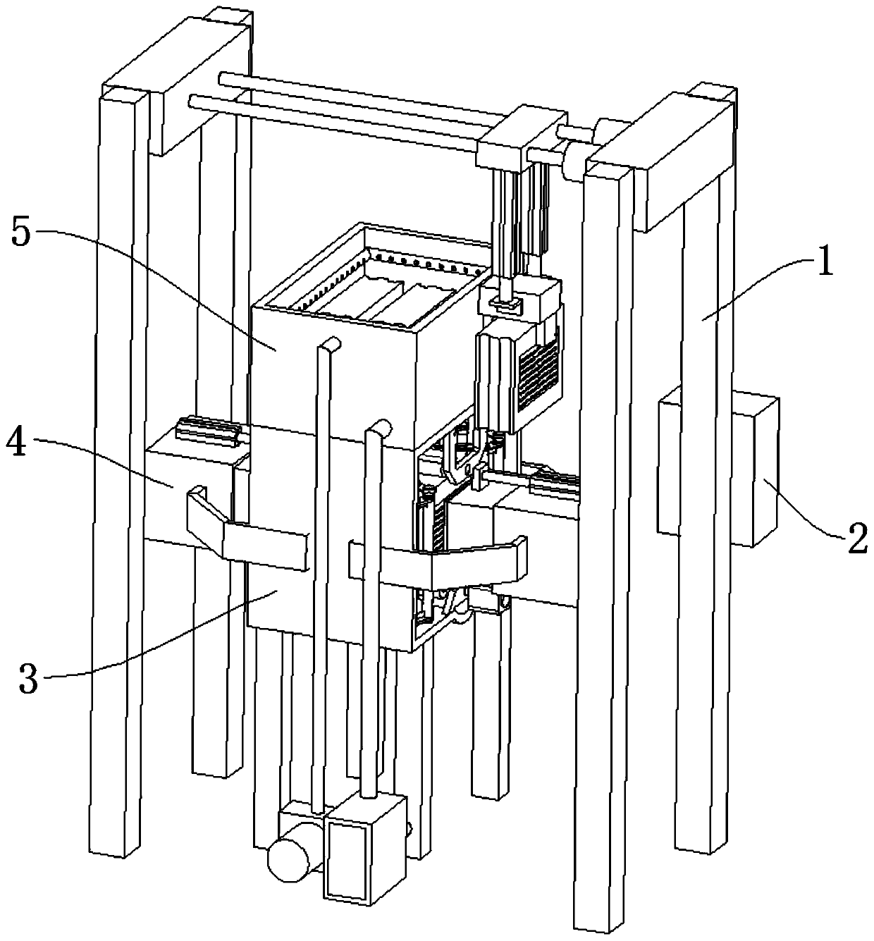
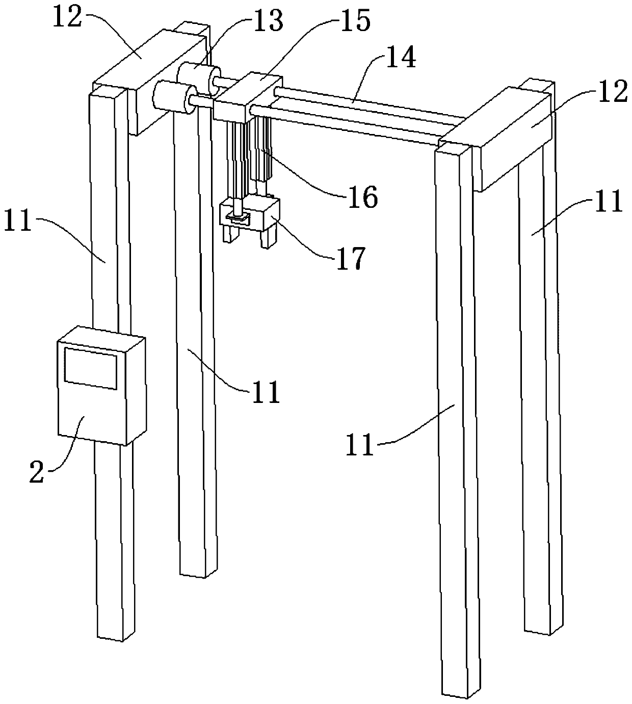
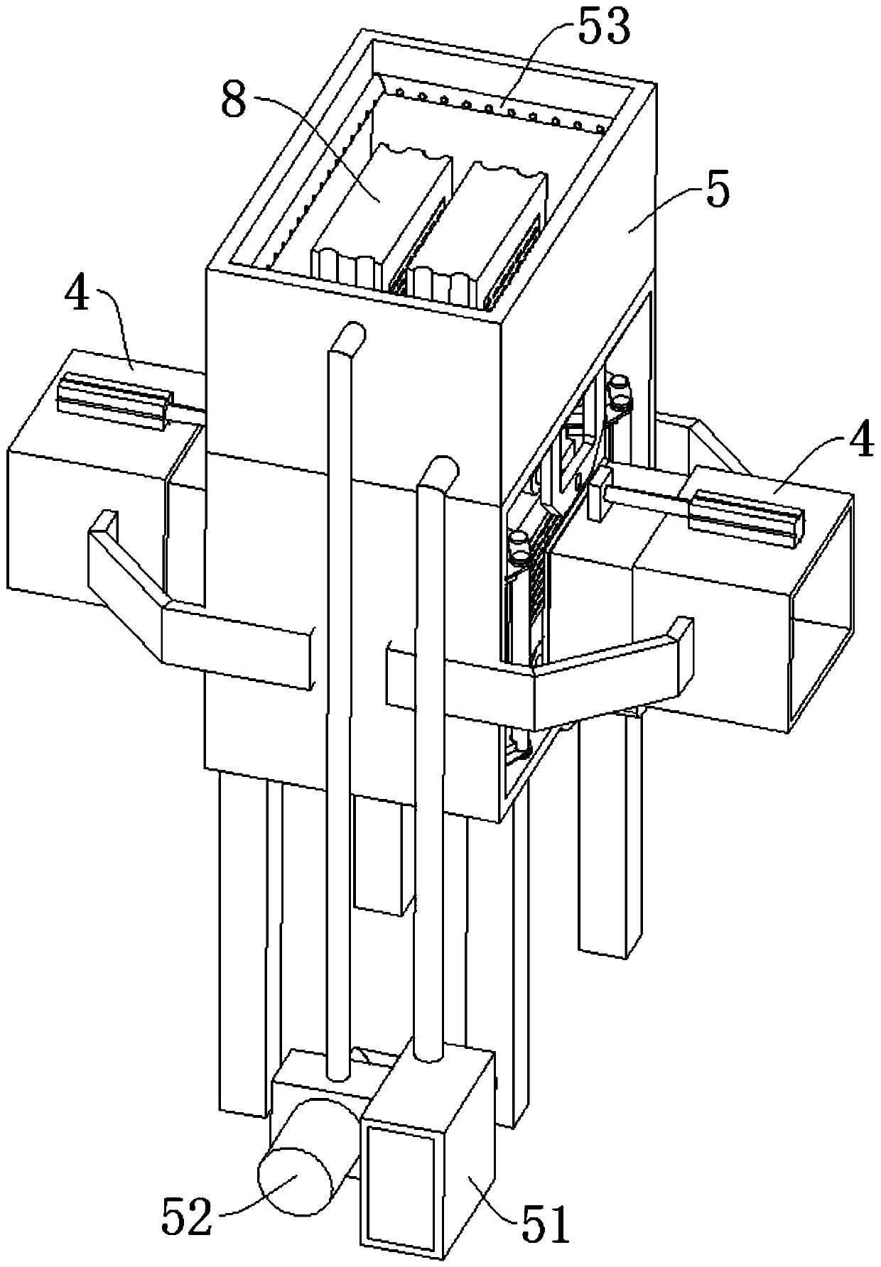
[0039] see Figure 1-11 , the present invention provides a technical solution: a plastic blow molding automatic screen changing structure, including a transport device 1 and a net change box 3, the side wall of the transport device 1 is fixedly connected with an electric control box 2, and the top of the net change box 3 is fixedly connected with a The cleaning box 5 and the two sides of the net changing box 3 are fixedly connected with two docking devices 4, and t...


PUM


Abstract

The invention discloses a working method of an automatic net changing structure for plastic blow molding, and relates to the technical field of plastic blow molding machines. A blow molding machine towhich the working method relates comprises a conveying device and a net changing box, wherein an electric control box is fixedly connected to one side wall of the conveying device; a cleaning box isfixedly connected to the top of the net changing box; two butt joint devices are fixedly connected to the two sides of the net changing box; two driving devices are arranged in the interior of the netchanging box; the inner bottom surface and inner top surface of the net changing box are both fixedly connected with lifting devices; and three filtering devices are movably connected between the twodriving devices. According to the working method, the driving devices and the conveying device are matched with one another, so that the automatic replacement of the filtering devices is realized, and the replaced filtering devices are sprayed and cleaned in the interior of the cleaning box to facilitate the recycling; the lifting devices can change the overlapping area of filtering holes and thereby changing the sizes of the filtering holes, so that impurities with different sizes and diameters are filtered away; and the impurities can also be sheared through the relative sliding of the filtering holes, and the rapid dredging can be realized.

Description

technical field [0001] The invention relates to the technical field of plastic blow molding machines, in particular to a working method of an automatic screen changing structure for plastic blow molding. Background technique [0002] A blow molding machine is a plastic processing machine. After the liquid plastic is sprayed out, the plastic body is blown and attached to a mold cavity of a certain shape by using the wind force blown out by the machine to make a product. This kind of machine is called a blow molding machine; during the production process of a blow molding machine, plastic After the melt is plasticized and heated for a long time, there will be decomposition residues in the melt, plus other impurities in the raw materials. Once they enter the machine head, they will cause blockage of the flow channel. In order to avoid the problem of blockage, usually A filter screen will be set between the barrel and the machine head. [0003] The existing filter screen repla...

Claims


Application Information

Patent Timeline
Patent Type & Authority Applications(China)
IPC IPC(8): B29C48/10B29C48/27B29C48/691B29C55/28
CPCB29C48/0017B29C48/10B29C48/2725B29C48/691B29C55/28
Inventor 段芳利李伟
Owner 广西膜宝包科技发展有限公司
Why Eureka
Eureka Blog
Learn More