
Automatic rotary tool rest structure for numerically controlled lathe

An automatic rotary and CNC lathe technology, applied in the direction of tool clamps, etc., can solve the problems of high rotation accuracy of the shaft, no protection device, and poor fixing ability, so as to improve the rotation accuracy and realize the effect of the rotation accuracy problem

Active Publication Date: 2020-08-07
江苏贵钰航空工业有限公司
View PDF12 Cites 0 Cited by
  • Summary
  • Abstract
  • Description
  • Claims
  • Application Information

AI Technical Summary

Problems solved by technology

[0004] The object of the present invention is to provide an automatic rotary tool rest structure for a numerically controlled lathe, to solve the problem of poor fixation ability proposed in the above-mentioned background technology, and no protection device is provided for the position limit of the tool rest seat during use, and for the rotation shaft The problem of high rotation accuracy

Method used


Image

  • Automatic rotary tool rest structure for numerically controlled lathe
  • Automatic rotary tool rest structure for numerically controlled lathe
  • Automatic rotary tool rest structure for numerically controlled lathe

Examples


Embodiment Construction

[0018] In order to make the purpose, technical solutions and advantages of the embodiments of the present invention clearer, the technical solutions in the embodiments of the present invention will be clearly and completely described below in conjunction with the accompanying drawings in the embodiments of the present invention. Obviously, the described embodiments It is some embodiments of the present invention, but not all of them. Based on the implementation manners in the present invention, all other implementation manners obtained by persons of ordinary skill in the art without creative efforts fall within the protection scope of the present invention. Accordingly, the following detailed description of the embodiments of the invention provided in the accompanying drawings is not intended to limit the scope of the claimed invention, but merely represents selected embodiments of the invention. Based on the implementation manners in the present invention, all other implement...


PUM


Abstract

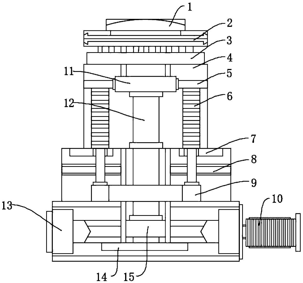
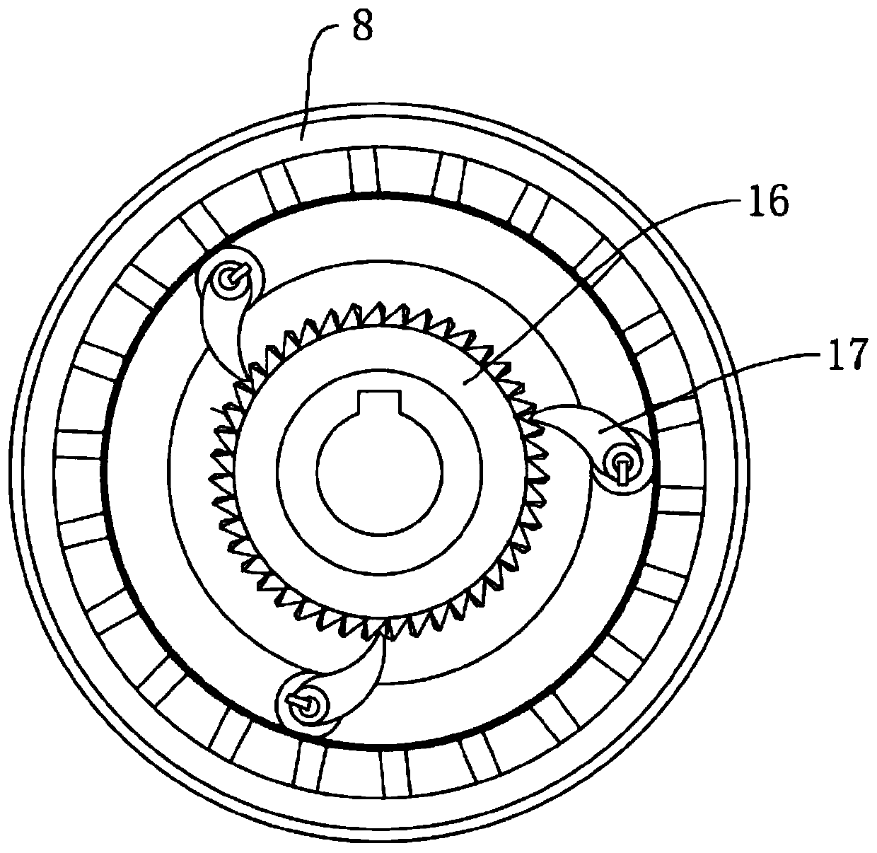
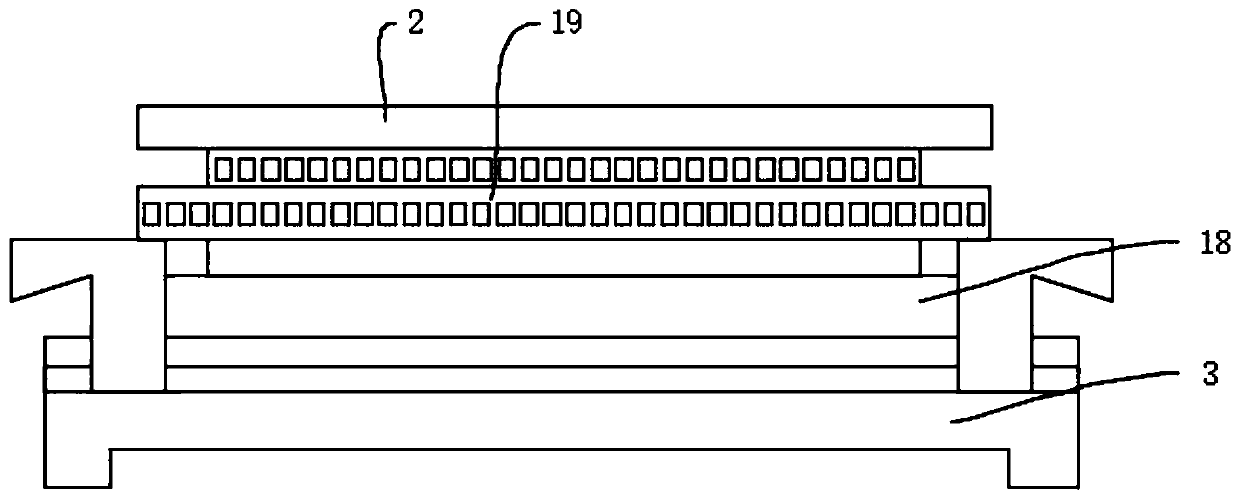
The invention discloses an automatic rotary tool rest structure for a numerically controlled lathe. The automatic rotary tool rest structure comprises a base, wherein a motor is installed at one end of the base, the motor is located in the middle of the base, a worm is installed in the base, the worm is located in the middle of the interior of the base, a fixing plate is installed at the bottom end of the worm, the fixing plate is located at the bottom end of the interior of the base, a rotating shaft is installed on the worm, the rotating shaft is located at the middle of the worm, and a rackis installed at the top end of the base. According to the automatic rotary tool rest structure for the numerically controlled lathe, the fixing plate is installed in the base to be connected with thebottom end position of the rotating shaft and limit the bottom end position of the rotating shaft at the same time, it is guaranteed that the position of the rotating shaft is fixed during worm transmission, and the protective problem when the worm rotates is effectively solved; and cylindrical pins are installed between a shaft sleeve and a disc to be fixedly connected with the position of a limiting disc, the rotating precision of the rotating shaft is further achieved, and the rotating precision of the tool rest base is improved.

Description

technical field [0001] The invention relates to the technical field of rotary tool holders, in particular to an automatic rotary tool holder structure for a numerically controlled lathe. Background technique [0002] The rotary tool post is used for CNC lathes. It can be installed on the turret head to hold various tools for different purposes. The automatic tool change action of the machine tool can be realized through the rotary indexing of the turret head. Its form generally has a vertical shaft type. And the horizontal axis type, the vertical axis type is generally a square or hexagonal tool holder, which can install four or six tools respectively; the horizontal axis type is usually a disc type rotary tool holder, which can install a large number of tools. [0003] There are many deficiencies in the rotary tool holder in the prior art; for example, the fixing ability is not good, and there is no protection device for the position limit of the tool holder seat during use...

Claims


Application Information

Patent Timeline
IPC IPC(8): B23B29/32
CPCB23B29/32Y02P70/10
Inventor 王海龙伍志健
Owner 江苏贵钰航空工业有限公司
Learn More