
Time-controlled intermittent life test method based on junction temperature real-time correction

A technology of life test and heating time, applied in semiconductor working life test, single semiconductor device test, instrument and other directions, can solve the problem of insufficient accuracy of intermittent life test, and achieve the effect of strict conditions and accurate test requirements.

Active Publication Date: 2020-08-04
西安太乙电子有限公司
View PDF10 Cites 1 Cited by
  • Summary
  • Abstract
  • Description
  • Claims
  • Application Information

AI Technical Summary

Problems solved by technology

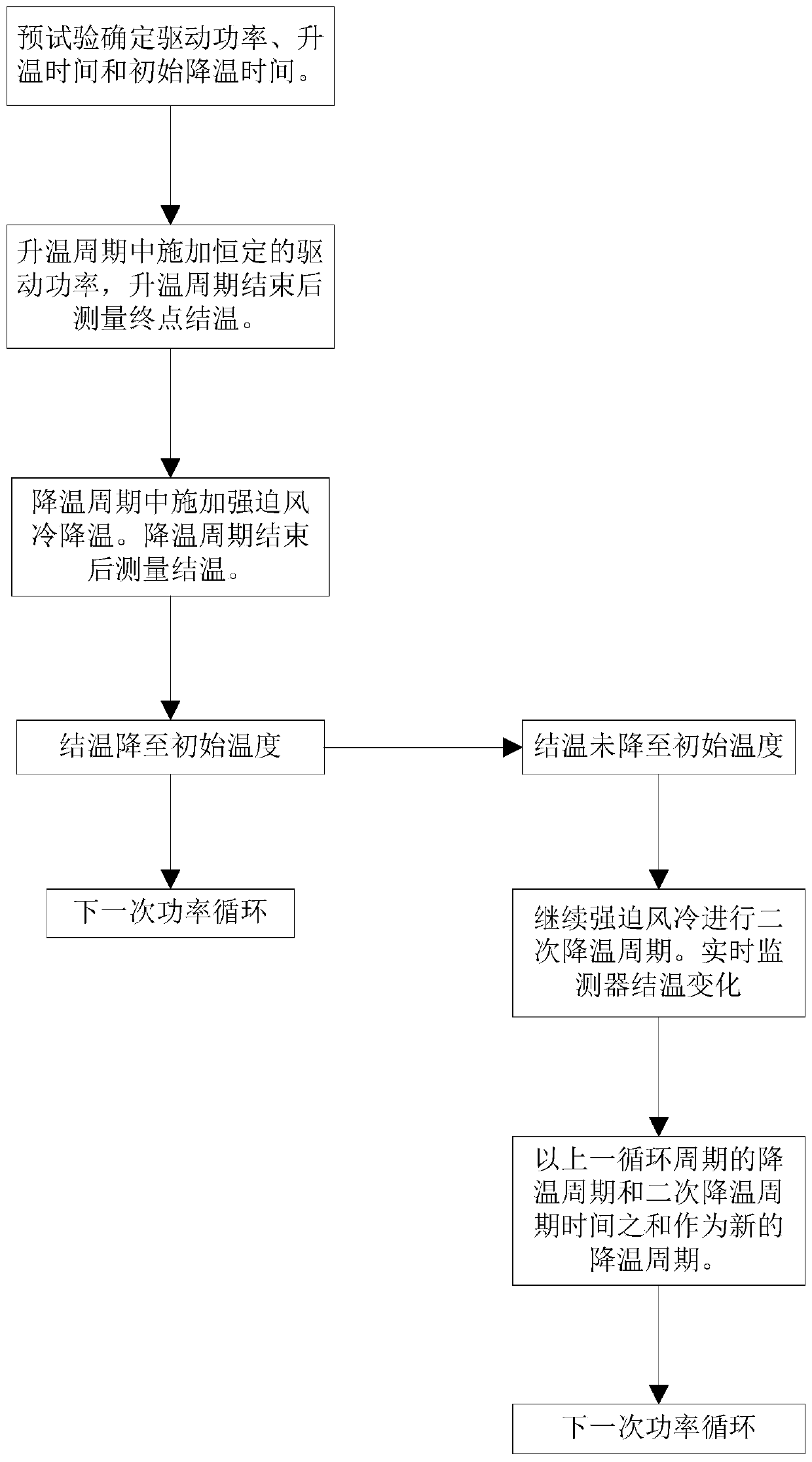
[0003] The object of the present invention is to solve the problem of insufficient accuracy of the intermittent life test in the prior art, to provide a time-controlled intermittent life test method based on real-time correction of the junction temperature, and to replace the case temperature measurement by the junction temperature measurement, thereby improving the junction temperature measurement The accuracy of the value; in the test process, by introducing feedback and modifying the cooling time in the test according to the junction temperature change, the reliability of the device and the compliance of the test conditions with the requirements of the national military standard can be more reasonably inspected

Method used


Image

  • Time-controlled intermittent life test method based on junction temperature real-time correction
  • Time-controlled intermittent life test method based on junction temperature real-time correction
  • Time-controlled intermittent life test method based on junction temperature real-time correction

Examples


Embodiment Construction

[0023] The present invention will be described in further detail below in conjunction with the accompanying drawings.

[0024] The implementation method of junction temperature monitoring in the test process of the present invention comprises the following contents:

[0025] This method needs to measure the junction temperature online during the test, and the influence of the measurement of the junction temperature on the test process should be minimized. Compared with the case temperature measurement, the junction temperature measurement cannot be directly carried out by external means such as thermocouples. In the implementation process of the present invention, it is necessary to use the indirect measurement of the junction temperature by monitoring the changes of temperature-sensitive electrical parameters.

[0026] For the relationship between the temperature-sensitive electrical parameters of specific devices and the junction temperature, it is necessary to apply a certa...


PUM


Abstract

A time-controlled intermittent life test method based on junction temperature real-time correction comprises the following steps that a sample is selected for a pre-test, temperature rise time of a junction temperature variable quantity, meeting a test requirement, of a specific device under driving power is determined, and the time when the junction temperature is reduced to an initial temperature is recorded; the temperature rise time measured by the pre-test is used as a temperature rise period of a cycle period, constant driving power is continuously applied in the temperature rise period,after the temperature rise period is finished, narrow pulse excitation is used for measuring an end point junction temperature of the device, and the temperature drop time measured by the pre-test isused as the temperature drop period for cooling the device; and after the temperature drop period is finished, if the junction temperature does not reach the initial temperature, a secondary temperature drop period is continued, wherein the next cycle period is equal to the sum of the time of the temperature drop period and the time of the secondary temperature drop period of the previous cycle period. In the invention, an intermittent working state of a component can be simulated more strictly, and an intermittent life test requirement can be met more accurately.

Description

technical field [0001] The invention belongs to the field of semiconductor reliability test, in particular to a time-controlled intermittent life test method which is corrected in real time according to the junction temperature. Background technique [0002] Intermittent life test is an important test item to ensure the quality and reliability of semiconductor discrete devices. By repeatedly energizing and powering off the device, and applying stress to the device regularly and intermittently, the reliability of the device is inspected. At present, most manufacturers monitor the junction temperature change required by the test by measuring the case temperature of the device when actually performing the intermittent life test. Due to differences in monitoring methods and standards, different heat dissipation environments and the temperature difference between junction temperature and case temperature of devices in different packaging forms may be large, and monitoring case te...

Claims


Application Information

Patent Timeline
Patent Type & Authority Applications(China)
IPC IPC(8): G01R31/26
CPCG01R31/2601G01R31/2642
Inventor 刘扬马瑜加徐卜
Owner 西安太乙电子有限公司
Learn More