
A plantar pressure wireless acquisition and display circuit and method thereof

A plantar pressure, wireless acquisition technology, applied in the fields of medical science, diagnosis, instruments, etc., can solve the problems of inconvenient portability and operation, high cost, inability to visually display human gait information in real time, etc., to reduce the amount of measurement data, practical strong effect

Active Publication Date: 2021-01-22
重庆旋易智能技术有限公司
View PDF10 Cites 0 Cited by
  • Summary
  • Abstract
  • Description
  • Claims
  • Application Information

AI Technical Summary

Problems solved by technology

The size and distribution of plantar pressure can directly reflect the information of the human leg, foot structure, function, and overall body posture control. Analyzing and evaluating plantar stress is of great significance for clinical diagnosis, disease degree measurement, and postoperative curative effect evaluation. With people's attention to plantar health in recent years, the importance of plantar pressure analysis in the field of clinical medicine and rehabilitation is increasing day by day. However, the traditional professional plantar pressure information collection and measurement devices are expensive and require the combination of upper computer and lower computer. Collect human gait information, but it is inconvenient to carry and operate, and cannot display human gait information intuitively in real time

Method used


Image

  • A plantar pressure wireless acquisition and display circuit and method thereof
  • A plantar pressure wireless acquisition and display circuit and method thereof
  • A plantar pressure wireless acquisition and display circuit and method thereof

Examples


Embodiment 1

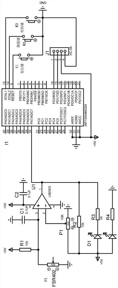
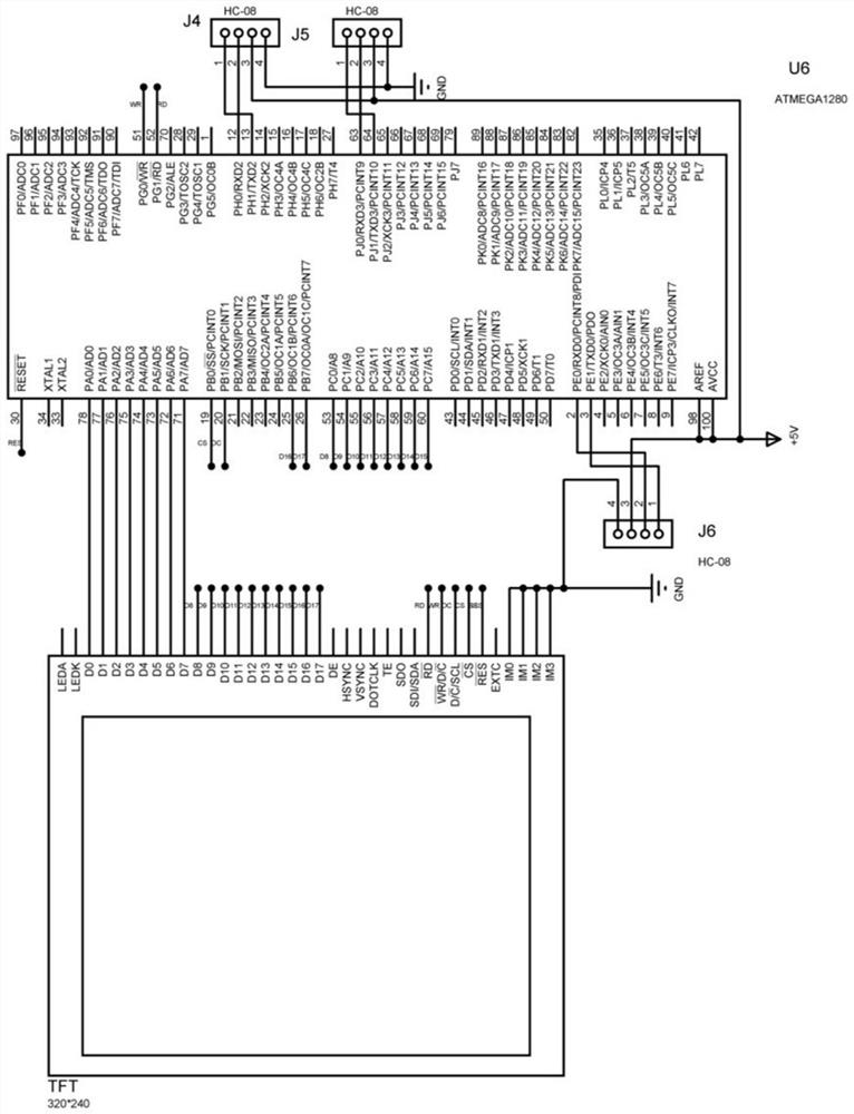
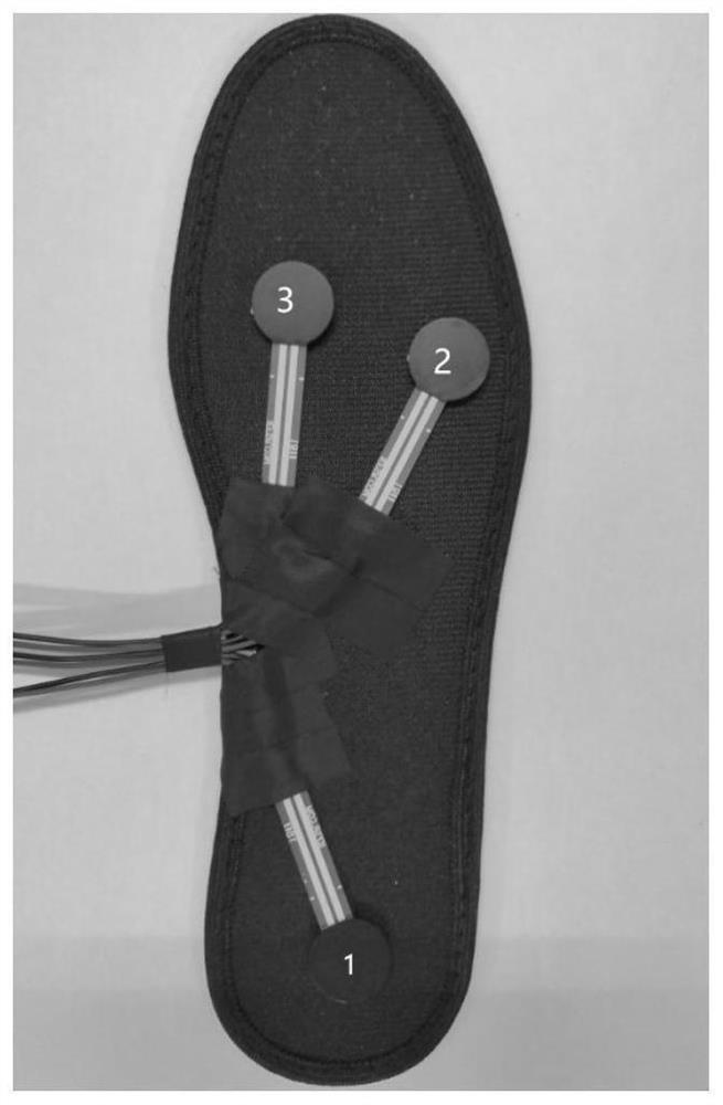
[0040] refer to figure 1 , the wireless plantar pressure acquisition circuit provided by the present invention includes a three-way plantar pressure signal acquisition circuit, and the three-way plantar pressure signal acquisition circuit corresponds to the signal receiving and bluetooth transmitting circuit connected sequentially, and the connection between all signal receiving and bluetooth transmitting circuits The information is gathered to the bluetooth receiving and display circuit for analysis and display.

[0041] The structure of the plantar pressure signal acquisition circuit is exactly the same, including pressure sensor F1, comparator U1, resistor R1, resistor R2, resistor R3, resistor R4, potentiometer P1, LED diode D1 and LED diode D2, and one end of pressure sensor F1 is grounded , the other end is electrically connected to the signal input end of the comparator U1, the signal input end of the comparator U1 is electrically connected to one end of the resistor R1...


PUM


Abstract

The invention relates to a wireless plantar pressure acquisition and display circuit, which belongs to the technical field of human plantar pressure measurement, and comprises a plurality of signal acquisition circuits respectively used for acquiring pressure values of different parts of a human plantar and converting the acquired pressure values into digital signals; a plurality of single-chip microcomputers which are electrically connected with the output ends of the corresponding signal acquisition circuits respectively and used for receiving digital signals of the pressure values of the planta pedis of the human body; a plurality of wireless transmitting modules which are electrically connected with the corresponding single-chip microcomputers respectively and are used for transmittingthe digital signals transmitted to the single-chip microcomputers by the signal acquisition circuits; a wireless receiving module which is used for receiving the digital signals transmitted by the plurality of wireless transmitting modules; and a main processor which is in signal connection with the wireless receiving module, and is used for receiving the digital signal sent by the wireless receiving module, judging and processing the digital signal, and transmitting a final gait phase result to the display for displaying. The device reduces the measurement data volume, is low in cost, and isconvenient to carry and operate.

Description

technical field [0001] The invention belongs to the technical field of human foot plantar data measurement, and in particular relates to a plantar pressure wireless collection and display circuit and a method thereof. Background technique [0002] Inconvenience in lower limb walking seriously affects the walking and daily life of stroke patients. In severe cases, it will cause lower limb movement disorders, functional degradation and even amputation. The analysis of plantar pressure and gait data has been relatively mature for the diagnosis and treatment of foot diseases, which has greatly promoted the development of clinical biomechanics. It provides an accurate evaluation method and basis for clinical rehabilitation evaluation, the fitting effect of orthopedic insole shoes, and the fitting effect of prosthetic orthotics. Therefore, relevant human physiological signal information can be obtained to help by analyzing plantar pressure changes. The size and distribution of p...

Claims


Application Information

Patent Timeline
Patent Type & Authority Patents(China)
IPC IPC(8): A61B5/103G08C17/02
CPCA61B5/0004A61B5/1038G08C17/02
Inventor 李华青袁野郑李逢吕庆国王政
Owner 重庆旋易智能技术有限公司
Learn More