a power control device

A power control and equipment technology, applied in electrical components, substation/switch layout details, substation/distribution enclosures, etc., can solve problems such as damage, condensation, and inability to prevent moisture, achieve faster response, expand contact area, and solve moisture problems Effect

Active Publication Date: 2021-11-30
BAIYIN POWER SUPPLY COMPANY STATE GRID GANSU ELECTRIC POWER
View PDF10 Cites 0 Cited by
  • Summary
  • Abstract
  • Description
  • Claims
  • Application Information

AI Technical Summary

Problems solved by technology

[0002] Power control equipment is a kind of control equipment that further controls the power lines. In rainy weather, some power control equipment used for outdoor exploration equipment will easily condense water mist on the surface, interior and operation panel of the equipment due to the increase in air humidity. , forming water droplets, there are defects that cannot prevent moisture, which increases the risk of leakage and equipment damage

Method used


Image

  • a power control device
  • a power control device
  • a power control device

Examples


Embodiment 1

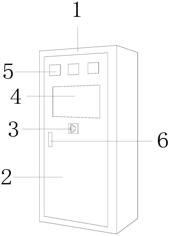
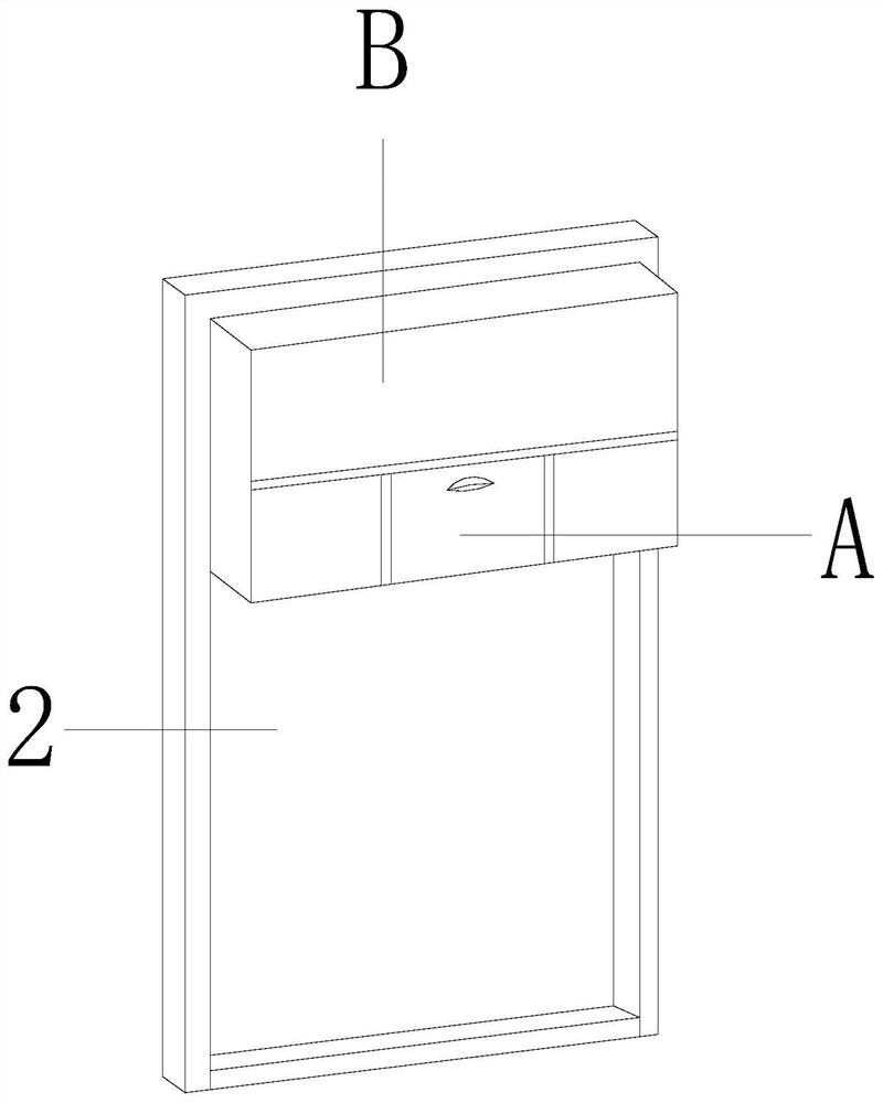
[0027] Such as Figure 1-Figure 6 Shown:

[0028] The present invention provides a kind of electric control equipment, its structure comprises cabinet body 1, cabinet door 2, knob 3, observation window 4, indicator light 5, handle 6, described cabinet door 2 and cabinet body 1 are hingedly connected, and described observation window 4. Embedded connection is directly in front of the cabinet door 2, the handle 6 is bolted to the left position in the middle of the cabinet door 2, the indicator light 5 is connected to the upper front of the cabinet door 2 with interference, and the knob 3 is movably engaged in the cabinet door 2. The middle position in front of the door 2; the cabinet door 2 mainly includes a fixed platform A and a drying mechanism B, and the drying mechanism B is bolted directly below the fixed platform A, and the fixed platform A and the drying mechanism B are embedded and connected in the cabinet Door 2 rear upper end.

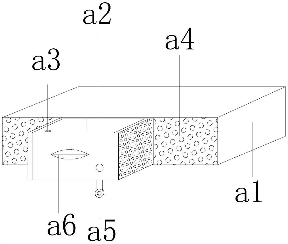
[0029] Wherein, the drying mechanism ...

Embodiment 2

[0036] Such as Figure 7-Figure 9 Shown:

[0037] The present invention provides a power control device. The moving device b3 mainly includes a track e1, an I-shaped moving wheel e2, a fixed block e3, and a brake mechanism e4. The track e1 is embedded and connected to the upper position inside the box body a1. The brake mechanism e4 is movably engaged with the I-shaped moving wheel e2, and the brake mechanism e4 is fixedly installed on both sides of the bottom of the box body a1 through the fixed block e3. There are two, and the left-right symmetrical structure is centered on the middle drawer groove b1.

[0038]Wherein, the brake mechanism e4 mainly includes a coupling rod f1, a rotating shaft f2, a joint block f3, a brake rod f4, a convex ball f5, an anti-skid block f6, a spring f7, and a push piece f8. The rotating shaft f2 is embedded and connected to The middle position of the I-shaped mobile wheel e2, the rotating shaft f2 is movably engaged with the joint block f3, th...


PUM


Abstract

The invention discloses an electric control device, the structure of which comprises a cabinet body, a cabinet door, a knob, an observation window, an indicator light, and a handle. It includes a fixed table and a drying mechanism, and the drying mechanism is bolted to the position directly below the fixed table. The invention moves forward by pulling the handle, and the I-shaped moving wheel cooperates with the track. By pressing the brake lever on the side of the moving device, the brake The rod will push the anti-slip block, so that the I-shaped moving wheel will stop moving, and the dry granules can be poured into the drawer slot, thus solving the problem of nowhere to place the dry granules. When the drawer is pushed back, the contact button on the top of the drawer will Pressed down by the box body, the driver is activated to cooperate with the blades to rotate, so that during the mixing process, the contact area of ​​the dry particles is enlarged, and the reaction with the moisture is accelerated, thus effectively solving the moisture situation inside the equipment.

Description

technical field [0001] The present invention relates to the field of electric power, and more specifically, relates to a power control device. Background technique [0002] Power control equipment is a kind of control equipment that further controls the power lines. In rainy weather, some power control equipment used for outdoor exploration equipment will easily condense water mist on the surface, interior and operation panel of the equipment due to the increase in air humidity. , forming water droplets, there are defects that cannot prevent moisture, which increases the risk of leakage and equipment damage. Contents of the invention [0003] The present invention provides a power control device aimed at the above problems. [0004] In order to achieve the above object, the present invention is achieved through the following technical solutions: a power control device, the structure of which includes a cabinet body, a cabinet door, a knob, an observation window, an indica...

Claims


Application Information

Patent Timeline
Patent Type & Authority Patents(China)
IPC IPC(8): H02B1/30H02B1/38H02B1/28H02B11/127
CPCH02B1/28H02B1/30H02B1/306H02B1/38H02B11/127
Inventor 林毓松
Owner BAIYIN POWER SUPPLY COMPANY STATE GRID GANSU ELECTRIC POWER
Why Eureka
Try Eureka