Flat infrared detection lens

An infrared detection and planar technology, applied in prisms, instruments, optics, etc., can solve problems such as narrow receiving surfaces

Active Publication Date: 2022-07-01
SHANGHAI SUPERIOR WEEK ELECTRONICS TECH
View PDF7 Cites 0 Cited by
  • Summary
  • Abstract
  • Description
  • Claims
  • Application Information

AI Technical Summary

Problems solved by technology

Only the honeycomb openings greater than 90 degrees will expand, thus solving the problem of narrow receiving surface

Method used


Image

  • Flat infrared detection lens
  • Flat infrared detection lens
  • Flat infrared detection lens

Examples


Embodiment 2

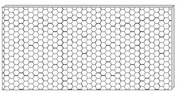
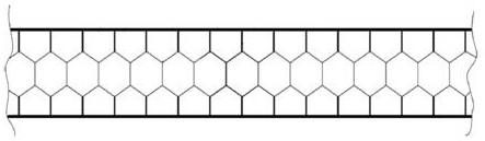
[0020] This embodiment improves the bottom surface on the basis of the above-mentioned embodiment. The improvement is that, firstly, the plate material has been positioned in the design stage, and secondly, according to the preset size, the receiving layer is Printing, the parts corresponding to the bottom surface are printed and colored; then the side walls are formed by stamping. When forming the side walls, it is required that the side walls do not need to be stretched. The method is to use the bottom heating method, that is, press After the die was in contact with the sheet for three seconds, a strong pressure was applied, whereby the bottom surface was stretched, while the thickness of the side wall was not changed. After the side wall is formed, the stamping head is changed, and the cold stamping method is still used at this time, so that the bottom surface is deformed, thereby forming the receiving layer. From the picture, I can see that after passing through the second...


PUM


Abstract

The invention relates to a lens structure, in particular to a flat infrared detection lens, which is composed of at least two layers, the top layer of which is a receiving layer, and the last layer is a transmission layer, characterized in that: the receiving layer is The surface is in the shape of a micro honeycomb, and each micro honeycomb in the surface of the receiving layer is composed of a multi-faceted side wall and a bottom with a plurality of reflective surfaces; each surface of the multi-faceted side wall and the horizontal plane are A certain angle; the angle is greater than 90 degrees; the bottom surface is provided with a plurality of reflective surfaces, the number of the reflective surfaces is the same as the number of side walls of the multi-sided side walls, and corresponds to the corresponding side walls; The side wall is provided with a reflective material; the bottom surface is provided with a light-absorbing material; the transmission layer is a transparent film; the transparent film is made of acrylic material with high light transmittance.

Description

technical field [0001] The present invention relates to a lens structure, in particular to a non-radian plane lens for infrared detectors. Background technique [0002] There are often far-infrared detection in the community, which is used to sense the intrusion of animals or people. Through the induction of heat, it is transmitted to the alarm to issue an alarm. In the installation of the far-infrared detector, there is a component, that is, the lens, whose function is to let the wavelength of thermal energy emitted from the outside pass through the lens and further enlarge; In this way, the number of use is reduced; on the one hand, the lenses used in the prior art must have a certain radian, that is, a curved surface, due to the function of the lens, the requirements of its technology and function; in addition, because the curved surface also The receiving surface can be increased. In the past, infrared detectors mainly used traditional single-beam PIR reflection focusi...

Claims


Application Information

Patent Timeline
Patent Type & Authority Patents(China)
IPC IPC(8): G02B5/04
CPCG02B5/045
Inventor 何驰
Owner SHANGHAI SUPERIOR WEEK ELECTRONICS TECH
Why Eureka
Try Eureka