
Lifting device and robot

A technology of lifting device and mounting seat, which is applied in the direction of supporting machines, transmission devices, instruments, etc., can solve the problems of large volume and complex structure, and achieve the effect of reducing system size, simple device and realizing protection

Inactive Publication Date: 2020-07-31
UBTECH ROBOTICS CORP LTD
View PDF9 Cites 10 Cited by
  • Summary
  • Abstract
  • Description
  • Claims
  • Application Information

AI Technical Summary

Problems solved by technology

[0003] The purpose of the embodiments of the present application is to provide a lifting device and a robot to solve the technical problems of complex structure and large volume caused by the transmission of multiple sets of screw structures in parallel in the existing lifting structure

Method used


Image

  • Lifting device and robot
  • Lifting device and robot
  • Lifting device and robot

Examples


Embodiment Construction

[0031] In order to make the technical problems, technical solutions and beneficial effects to be solved by the present application clearer, the present application will be further described in detail below in conjunction with the accompanying drawings and embodiments. It should be understood that the specific embodiments described here are only used to explain the present application, and are not intended to limit the present application.

[0032] In the description of the embodiments of the present application, it should be understood that the terms "length", "width", "upper", "lower", "front", "rear", "left", "right", "vertical ", "horizontal", "top", "bottom", "inner", "outer" and other indicated orientations or positional relationships are based on the orientations or positional relationships shown in the drawings, and are only for the convenience of describing the embodiments of the present application and simplifying Describes, but does not indicate or imply that the dev...


PUM


Abstract

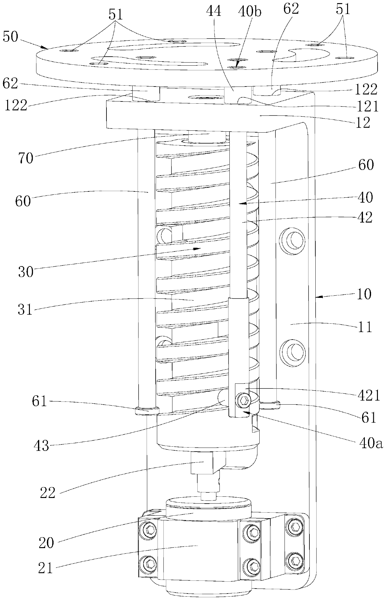
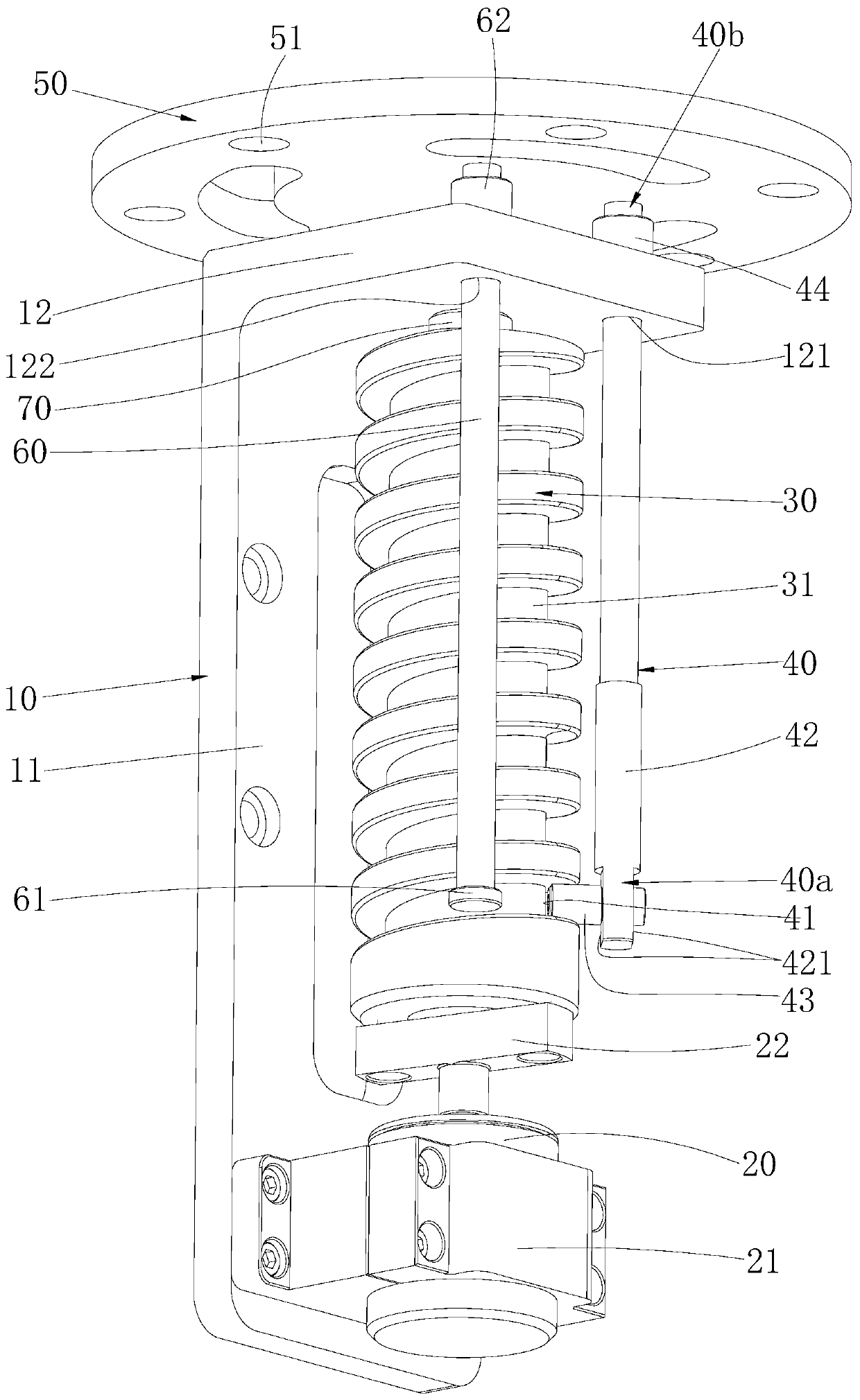
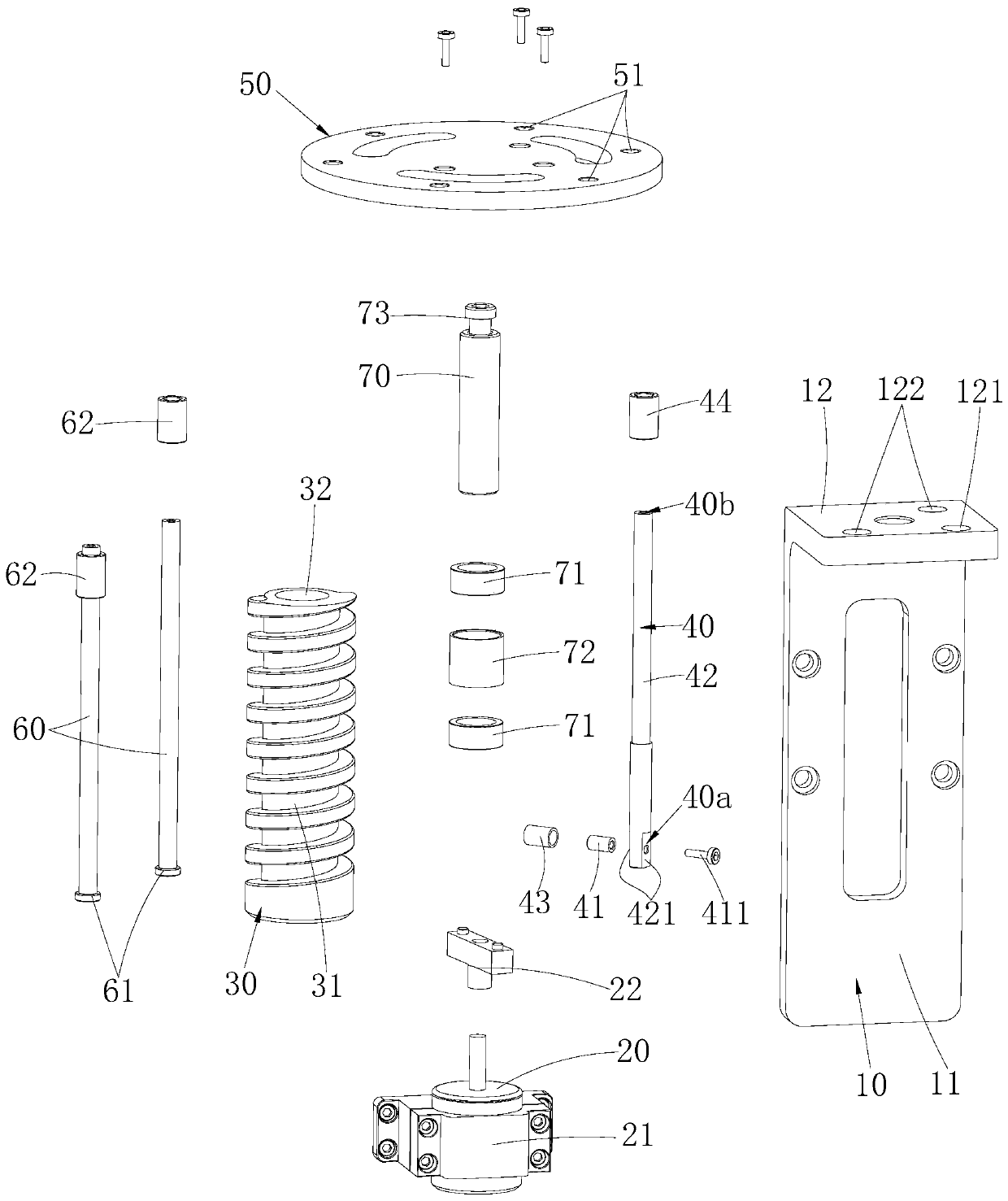
The invention belongs to the technical field of robot accessories, and particularly relates to a lifting device and a robot. According to the lifting device, a rotating driving part is used for driving a cam to rotate, a cam rod penetrates through a mounting base, and a matching column of the cam rod stretches into a spiral groove of the cam. When the cam rotates, the matching column can move in the spiral groove, and the inner wall of the spiral groove applies force to the matching column along a cam shaft, so that the cam rod slides relative to the mounting base, and thus a connecting base connected with the cam rod moves relative to the mounting base. According to the robot with the lifting device, a lifted part is mounted on the connecting base, so that the lifting movement of the lifted part can be achieved. The mounting base, the cam and the cam rod are matched, and the device is simple, so that the system size is reduced. The lifting device serves as a modular structure and canbe quickly mounted to a place requiring a lifting function, such as a vehicle body of an existing automatic inspection robot. During operation, the lifted part is lifted, and the lifted part drops during non-operation, so that the lifted part is protected.

Description

technical field [0001] The application belongs to the technical field of robot accessories, and in particular relates to a lifting device and a robot. Background technique [0002] Robotic radar is the core device for inspection robots to detect the external environment for navigation. The device is relatively precise and expensive. However, the existing outdoor inspection robots have their radar devices exposed outside. When they are not working, Exposure to the outside will accelerate the damage of the device. Considering its service life, some robots use some lifting structures to realize the lifting function of the radar during work. The common device uses a ball screw structure, and the four sets of screw structures pass through the belt structure. Parallel connection, by driving the screw to rotate, the up and down movement of the nut is used to promote the lifting function of the lidar. However, the structure is complex, the installation requirements are high, and th...

Claims


Application Information

Patent Timeline
Patent Type & Authority Applications(China)
IPC IPC(8): F16M11/04F16M11/18F16M11/42F16H25/12G01S7/481
CPCF16M11/046F16M11/04F16M11/18F16M11/42F16H25/12G01S7/481F16M7/00F16H25/18B25J9/126F16H25/20F16H2025/204F16H2025/2075F16M13/022
Inventor 赵永进余文华周礼兵牟俊鑫覃甲林熊友军
Owner UBTECH ROBOTICS CORP LTD
Learn More