
A coupled treatment system and method based on circulating flue gas and desulfurization wastewater

A technology for desulfurization wastewater and circulating flue gas, which is applied in gaseous discharge wastewater treatment, water/sewage treatment, water/sludge/sewage treatment, etc. It can reduce energy consumption, save energy, and prolong the maintenance period.

Active Publication Date: 2022-03-29
CHINA ENERGY ENG GRP GUANGDONG ELECTRIC POWER DESIGN INST CO LTD
View PDF4 Cites 0 Cited by
  • Summary
  • Abstract
  • Description
  • Claims
  • Application Information

AI Technical Summary

Problems solved by technology

Although the unit-based desulfurization wastewater treatment system operates flexibly and is not restricted by unit maintenance, for a coal-fired power plant with multiple secondary reheat units, the overall investment in equipment is relatively high, and resource utilization is very unreasonable
[0008] (2) The process energy consumption of the existing desulfurization wastewater bypass flue evaporation treatment system is too large. Taking a 1000MW double reheating large-scale coal-fired unit in China as an example, the desulfurization wastewater volume of the two units is about 20t / h. Using the existing desulfurization wastewater bypass flue evaporation treatment system, the increased energy consumption of 2 units is about 50x10 6 kJ / h, the coal consumption of converted standard coal for power supply increases by about 0.8g / kWh to 0.9g / kWh
[0009] (3) Coal-fired secondary reheating units usually use hot smoke recirculation to adjust the reheating steam temperature. The hot smoke delivered by the circulating fan has a high dust concentration, the equipment has poor working conditions, and frequent maintenance has affected the overall reliability of the unit.

Method used


Image

  • A coupled treatment system and method based on circulating flue gas and desulfurization wastewater

Examples


Embodiment Construction

[0035] The specific implementation manners of the present invention will be further described in detail below in conjunction with the accompanying drawings and embodiments. The following examples are used to illustrate the present invention, but are not intended to limit the scope of the present invention.

[0036] In the description of the present invention, it should be noted that the terms "upper", "lower", "front", "rear", "left", "right", "vertical", "horizontal", "top", The orientation or positional relationship indicated by "bottom", "inner", "outer", etc. is based on the orientation or positional relationship shown in the drawings, and is only for the convenience of describing the present invention and simplifying the description, rather than indicating or implying the referred device or positional relationship. Elements must have certain orientations, be constructed and operate in certain orientations, and therefore should not be construed as limitations on the invent...


PUM


Abstract

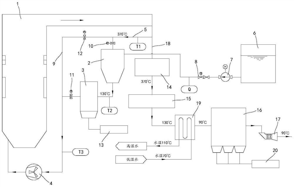
The invention relates to the technical field of wastewater treatment, and discloses a coupled treatment system based on circulating flue gas and desulfurization wastewater, including an evaporation crystallization system, a circulating flue gas system, and a flue gas exhaust system; a boiler, an evaporative crystallizer, a first dust collector and The circulation fans are connected through pipelines to form a circulation flue gas channel, and the circulation hot smoke is used as a heat source for evaporation and crystallization, and then enters the first dust collector for dust removal treatment, and finally is sent back to the boiler through the circulation fan; boiler, SCR reactor , the air preheater, the second dust collector and the induced draft fan are connected through pipelines to form a flue gas exhaust channel. While completing the evaporation treatment of unit desulfurization wastewater, the above-mentioned system realizes the classification treatment of high-chloride fly ash and ordinary fly ash, reduces the energy consumption of circulating fan operation, and greatly improves the treatment capacity of unit desulfurization wastewater. In addition, the present invention also provides a coupled treatment method based on circulating flue gas and desulfurization wastewater.

Description

technical field [0001] The invention relates to the technical field of wastewater treatment, in particular to a system and method based on the coupled treatment of circulating flue gas and desulfurization wastewater. Background technique [0002] At present, wet limestone-gypsum flue gas desulfurization technology (FGD) is the most widely used desulfurization technology in coal-fired power plants. It is suitable for a wide range of coal types, has strong adaptability to unit load changes, high desulfurization efficiency, and mature technology. In order to maintain normal operation and control the concentration of chloride ions in the circulating slurry, the limestone-gypsum desulfurization system needs to discharge part of the wastewater, that is, the desulfurization wastewater. Desulfurization wastewater has the following characteristics: (1) The wastewater has high turbidity and a large content of suspended solids (gypsum particles, SiO 2 , Al and Fe hydroxides), the conc...

Claims


Application Information

Patent Timeline
Patent Type & Authority Patents(China)
IPC IPC(8): C02F1/16B01D49/00C02F103/18
CPCC02F1/16B01D49/00C02F2103/18
Inventor 尹进
Owner CHINA ENERGY ENG GRP GUANGDONG ELECTRIC POWER DESIGN INST CO LTD
Learn More