
LED lamp bead and LED display structure

A technology of LED lamp bead and lamp body, which is applied in the direction of printed circuit and electrical components connected with instruments, non-printed electrical components, etc., which can solve the problems of punching, increase the difficulty and cost of PCB design, and avoid punching, Effect of reducing wiring difficulty and manufacturing cost

Inactive Publication Date: 2020-07-28
SHENZHEN AOTO ELECTRONICS
View PDF6 Cites 3 Cited by
  • Summary
  • Abstract
  • Description
  • Claims
  • Application Information

AI Technical Summary

Problems solved by technology

[0004] Based on this, it is necessary to provide an LED lamp bead and an LED display for the problem that when the traditional LED lamp bead is mounted on the lamp board, a multi-layer PCB needs to be used, and holes need to be drilled, which increases the difficulty and cost of PCB design. structure

Method used


Image

  • LED lamp bead and LED display structure
  • LED lamp bead and LED display structure
  • LED lamp bead and LED display structure

Examples


Embodiment Construction

[0036] In order to facilitate the understanding of the present application, the present application will be described more fully below with reference to the relevant drawings. Preferred embodiments of the application are shown in the accompanying drawings. However, the present application can be embodied in many different forms and is not limited to the embodiments described herein. On the contrary, the purpose of providing these embodiments is to make the disclosure of the application more thorough and comprehensive.

[0037] It should be noted that when an element is referred to as being “fixed” to another element, it can be directly on the other element or there can also be an intervening element. When an element is referred to as being "connected to" another element, it can be directly connected to the other element or intervening elements may also be present. The terms "vertical," "horizontal," "left," "right," and similar expressions are used herein for purposes of ill...


PUM


Abstract

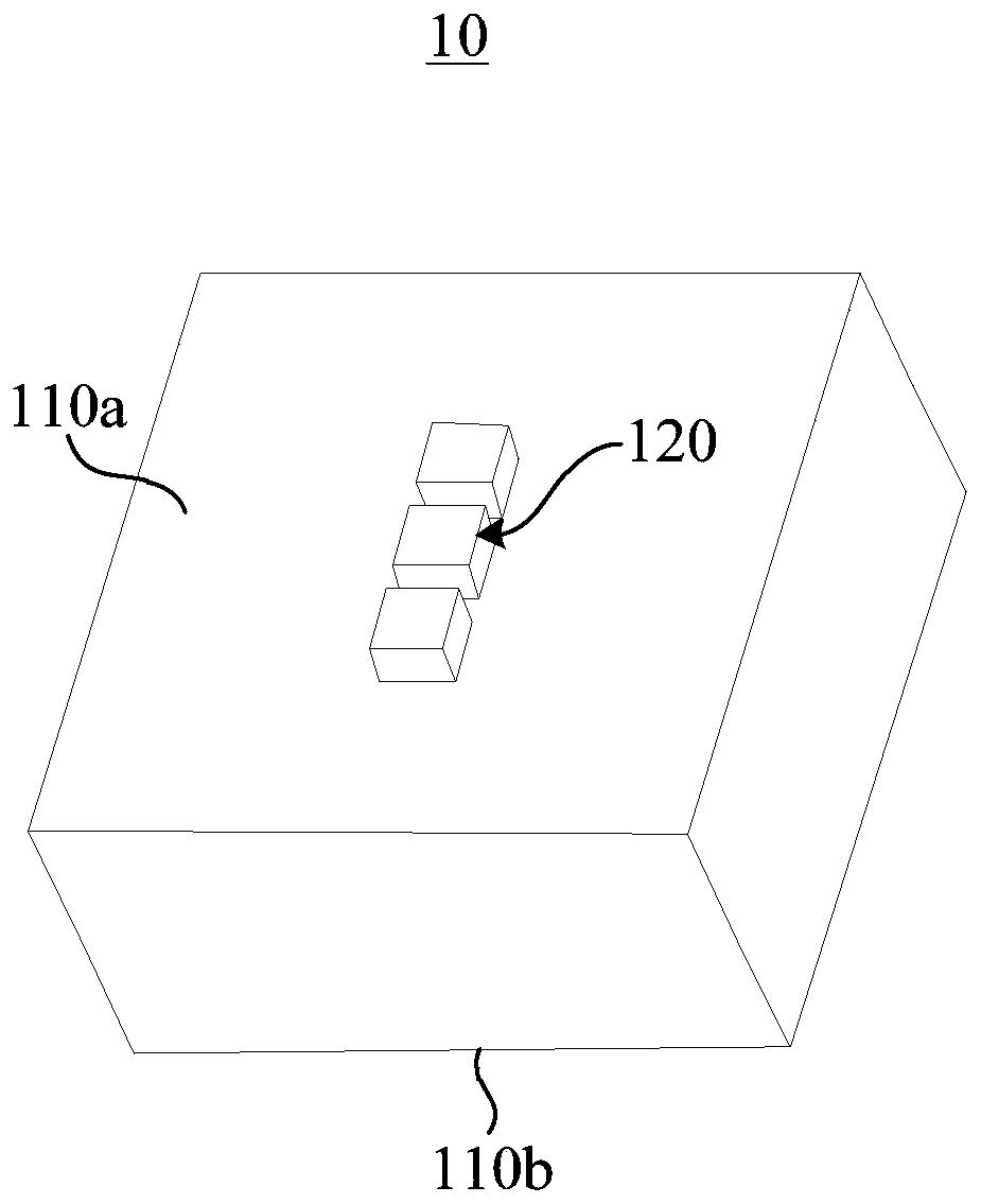
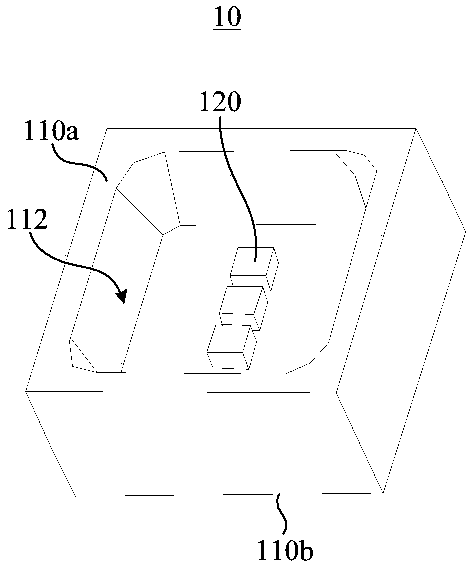
The invention relates to an LED lamp bead and an LED display structure. The LED lamp bead comprises a lamp body, a light-emitting chip set and pins, wherein the light-emitting chip set is arranged onthe first end face of the lamp body, the pins are arranged on the second end face of the lamp body, the light-emitting chip set comprises at least one light-emitting chip, the pins comprise color signal pins and row signal pins, the number of the row signal pins is at least two, every two row signal pins of the same LED lamp bead are paired, one pair of row signal pins is electrically connected with each other through a circuit in the lamp body, one of the pair of row signal pins which are electrically connected with each other is directly connected with the electrode of the light-emitting chip, the other row signal pin is a redundant row signal pin, and the LED lamp beads are attached to PCB to form an LED display structure. By providing the redundant row signal pins, the color signal circuit and the row signal circuit can be arranged on the same layer of the PCB, so that the wiring difficulty and the manufacturing cost of the PCB are reduced.

Description

technical field [0001] The present application relates to the field of LED display, in particular to an LED lamp bead and an LED display structure. Background technique [0002] LED displays are widely used in more and more scenes such as outdoor display, monitoring center, advertising / media display, stage, etc. To realize a large-area LED display, it is necessary to connect the LED lamp beads into a matrix through a circuit, and then control the light emission of the lamp bead matrix through a control chip to achieve a variety of displays. At present, the LED lamp beads are usually mounted on the PCB board, and the LED lamp beads are arranged in an array on the PCB board and connected through the lines on the PCB board. [0003] Traditional LED lamp beads are generally equipped with 4 pins, which are R, G, B, and C pins, among which the R, G, and B pins correspond to the R chip, G chip, and B chip respectively, and the C pin is the row signal pin. foot. In the connection...

Claims


Application Information

Patent Timeline
Patent Type & Authority Applications(China)
IPC IPC(8): G09F9/33H05K1/18H01L25/075H01L33/48H01L33/62
CPCG09F9/33H01L25/0753H01L33/48H01L33/62H05K1/18
Inventor 谢明璞李选中吴振志吴涵渠
Owner SHENZHEN AOTO ELECTRONICS
Learn More