
Micro-ring electro-optical modulator based on lithium niobate single crystal film, use method and application

An electro-optical modulator, single crystal thin film technology, applied in electromagnetic receivers, optics, instruments, etc., can solve the problems of reducing modulation efficiency, limiting the development of photonic radio frequency receiving front-end, etc., to reduce power consumption, increase length, and filter out interference. Effect

Pending Publication Date: 2020-07-28
UNITED MICROELECTRONICS CENT CO LTD
View PDF7 Cites 9 Cited by
  • Summary
  • Abstract
  • Description
  • Claims
  • Application Information

AI Technical Summary

Problems solved by technology

However, most of the modulators used in the existing RF photon receiving front-end are MZI electro-optic modulators. As the modulation frequency increases, the need for a large driving voltage will increase, and the modulation efficiency will decrease, greatly limiting the photon The development of radio frequency receiving front end, above-mentioned problem is the problem that needs to be solved urgently in this field

Method used

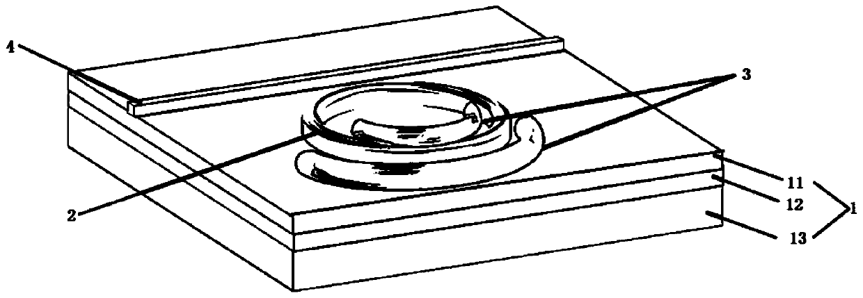

Image

  • Micro-ring electro-optical modulator based on lithium niobate single crystal film, use method and application
  • Micro-ring electro-optical modulator based on lithium niobate single crystal film, use method and application
  • Micro-ring electro-optical modulator based on lithium niobate single crystal film, use method and application

Examples


Embodiment Construction

[0029] The present invention will be further described below in conjunction with the accompanying drawings and specific embodiments, so that those skilled in the art can better understand the present invention and implement it.

[0030] A number of different implementations or examples of implementing the described subject technical solutions are disclosed below. In order to simplify the disclosure, the following describes specific embodiments of one or more permutations of each feature, but the examples cited are not intended to limit the present invention, and the first feature described later in the specification is connected to the second feature, namely It may include an embodiment that is directly connected, and may also include an embodiment that forms additional features. Further, it also includes the use of one or more other intervening features to indirectly connect or combine the first feature and the second feature with each other, so that the first feature and The...


PUM


Abstract

The invention provides a micro-ring electro-optical modulator based on a lithium niobate single crystal thin film, a use method and application. The micro-ring electro-optical modulator comprises thelithium niobate single crystal thin film and electrodes; the lithium niobate single crystal thin film comprises a micro-ring structure and an optical waveguide; the micro-ring structure and the optical waveguide are both arranged on the side, provided with lithium niobate, of the lithium niobate single crystal thin film; and the electrodes are respectively arranged on the inner side of the micro-ring structure and the outer side of the micro-ring structure. According to the micro-ring electro-optical modulator based on the lithium niobate single crystal thin film of the invention, the micro-ring structure is adopted, and therefore, the length of an electro-optic effect is increased, the driving voltage of the modulator is reduced, the power consumption of the device is reduced, and the receiving sensitivity of a radio frequency front end can be improved.

Description

technical field [0001] The invention relates to the field of electro-optic modulators, in particular to a micro-ring electro-optic modulator based on a lithium niobate single crystal thin film, a use method and an application. Background technique [0002] Microwave links are an important part of today's wireless communication systems. With the increase of communication capacity demand, high-frequency microwave signal is required as the carrier. However, with the increase of microwave signal frequency, the signal attenuation is very serious in the cable, and electronic components are severely restricted by electronic bottlenecks, which cannot meet the high-speed requirements. Microwave photonic technology combines the characteristics of microwave technology and photonic technology. It has the characteristics of large bandwidth, high speed, low loss, low noise and large dynamic range. It can effectively overcome the bottleneck problems of loss and electronic devices in microw...

Claims


Application Information

Patent Timeline
Patent Type & Authority Applications(China)
IPC IPC(8): G02F1/03G02F1/035H04B10/69
CPCG02F1/0316G02F1/035G02F1/0311H04B10/691
Inventor 杨明祥崔乃迪杨忠华梁宇鑫冯靖李智慧廖海军陈仙冯俊波郭进
Owner UNITED MICROELECTRONICS CENT CO LTD
Learn More