Eureka AIR delivers breakthrough ideas for toughest innovation challenges, trusted by R&D personnel around the world.

Cam coaxial sinusoidal motion mechanism and equipment adopting cam coaxial sinusoidal motion mechanism

A sinusoidal motion, camshaft technology, applied in mechanical equipment, machines/engines, transmissions, etc., can solve the problems of low mechanical efficiency and volumetric efficiency, high and low pressure return flow of cylinders, complex balancing mechanism, etc., to achieve compact structure and reduced noise. , the effect of reducing noise pollution

Pending Publication Date: 2020-07-28
NINGBO TIANSHENG SEALING PACKING
View PDF0 Cites 0 Cited by
  • Summary
  • Abstract
  • Description
  • Claims
  • Application Information

AI Technical Summary

Problems solved by technology

[0002] In the prior art, the conversion mechanism of rotation and reciprocating linear motion is usually a crank linkage mechanism, but the crank linkage mechanism has obvious disadvantages. Due to the structural characteristics of the crank linkage, there is side pressure during the movement of the linkage, and the mechanical efficiency and volumetric efficiency Low, a lot of progress has been made in the improvement of the crank-link mechanism, but the existing improved mechanism still has the following problems: the vibration is difficult to balance during the movement of the mechanism, there is high-order jitter, and the balance mechanism is complicated; the high and low pressure return flow of the cylinder during high-speed movement Serious phenomenon

Method used


Image

  • Cam coaxial sinusoidal motion mechanism and equipment adopting cam coaxial sinusoidal motion mechanism
  • Cam coaxial sinusoidal motion mechanism and equipment adopting cam coaxial sinusoidal motion mechanism
  • Cam coaxial sinusoidal motion mechanism and equipment adopting cam coaxial sinusoidal motion mechanism

Examples


Embodiment Construction

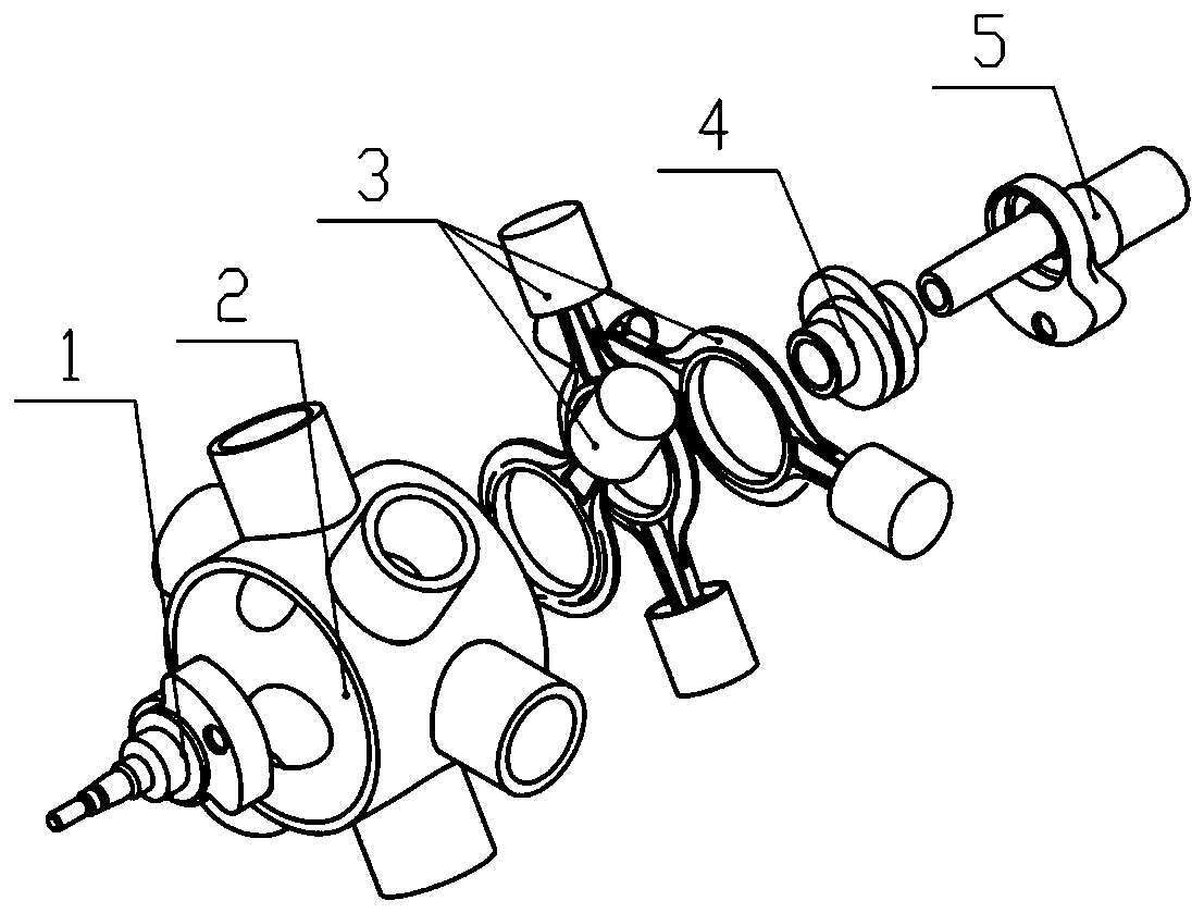
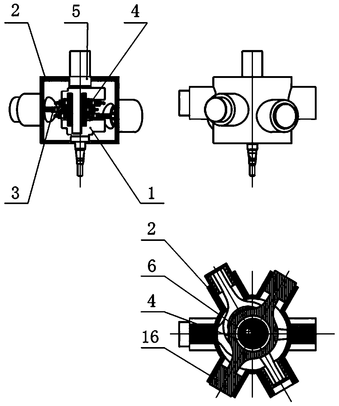
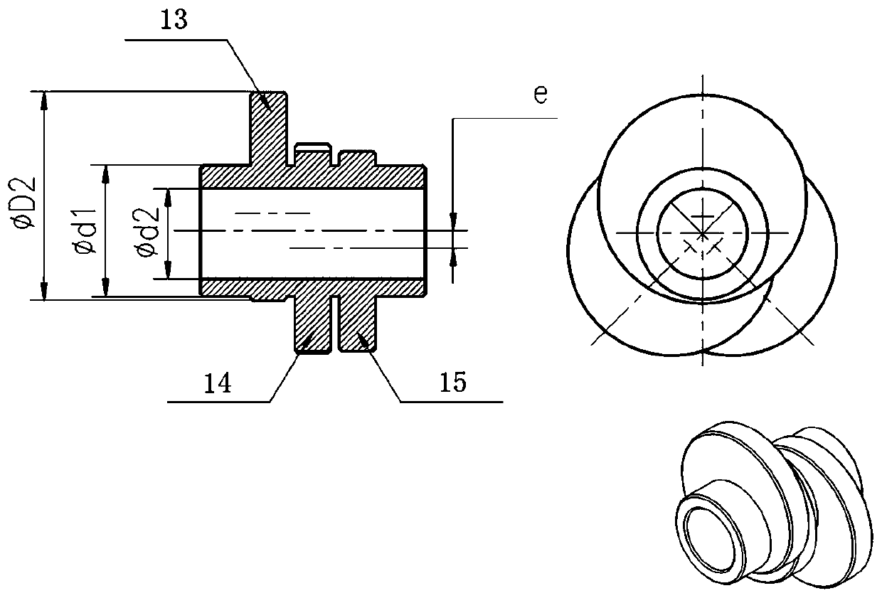
[0021] In this embodiment, the reciprocating rod is a piston rod, such as figure 1 As shown, the cam coaxial sinusoidal motion mechanism includes: eccentric circular camshaft 4, reciprocating rod 3, motion restraint body 2, crankshaft; crankshaft includes input-output shaft 5, crank (7, 11), crankshaft 1 and synchronous Axis 6. The eccentric circular camshaft 4 is sleeved on the synchronous shaft 6 of the input-output shaft 5 and is coaxial with the synchronous shaft 6. The synchronous shaft 6 is arranged between the two cranks and is fixedly connected with the cranks (7, 11); the reciprocating rod 3 can be The movement restrains the reciprocating linear motion in the body 2 . The motion-constrained body 2 is flexibly connected with the crankshaft 1 and the input-output shaft 5, and the crankshaft can rotate in the motion-constrained body. The crank (7, 11) and the eccentric circular camshaft 4 and the input-output shaft 5 form a combined crank camshaft component, and the ec...


PUM


Abstract

The invention discloses a cam coaxial sinusoidal motion mechanism and equipment adopting the cam coaxial sinusoidal motion mechanism. In the mechanism, conversion of reciprocating linear motion and rotating motion is achieved through cooperation of an eccentric round cam shaft and a reciprocating motion rod, and the mechanism comprises the eccentric round cam shaft, the reciprocating motion rod, amotion constraint machine body and a crankshaft. Motion of the mechanism is reasonable, only rotating centrifugal force is generated, no high order shaking is generated, balancing is extremely easy to achieve, no vibration is generated, the mechanical efficiency and the volume efficiency are high, the energy utilization rate is high, emissions are reduced, and the energy saving effect is good.

Description

technical field [0001] The invention relates to a conjugate sinusoidal reciprocating rotary motion mechanism, specifically a cam coaxial sinusoidal motion mechanism, and meanwhile, the invention also relates to equipment using the cam coaxial sinusoidal motion mechanism. Background technique [0002] In the prior art, the conversion mechanism of rotation and reciprocating linear motion is usually a crank linkage mechanism, but the crank linkage mechanism has obvious disadvantages. Due to the structural characteristics of the crank linkage, there is side pressure during the movement of the linkage, and the mechanical efficiency and volumetric efficiency Low, a lot of progress has been made in the improvement of the crank-link mechanism, but the existing improved mechanism still has the following problems: the vibration is difficult to balance during the movement of the mechanism, there is high-order jitter, and the balance mechanism is complicated; the high and low pressure re...

Claims


Application Information

Patent Timeline
Patent Type & Authority Applications(China)
IPC IPC(8): F16H21/20F16H35/16F04B9/04
CPCF16H21/20F16H35/16F04B9/04
Inventor 蔡勇励行根励洁魏世军李征罗文军岑冲王燕陈腾翔沈锴
Owner NINGBO TIANSHENG SEALING PACKING
Why Eureka
Eureka Blog
Learn More