Steel casing pulling-removal method

A steel casing and steel plate technology, which is applied in construction, sheet pile walls, and foundation structure engineering, can solve the problems that cannot be applied in permeable strata, the casing cannot be removed, and the air pressure control is complicated, so as to improve construction efficiency and speed up removal progress, wide range of effects

Inactive Publication Date: 2020-07-28
CCCC SECOND HARBOR ENG
View PDF5 Cites 1 Cited by
  • Summary
  • Abstract
  • Description
  • Claims
  • Application Information

AI Technical Summary

Problems solved by technology

For the removal of the steel casing, the removal needs to overcome the self-weight of the steel casing and the frictional resistance of the formation. Large-scale lifting equipment is often used to pull it out. tearing, the casing cannot be pulled out, and this method is not applicable to the limited use of large equipment; the air pressure jacking method, after the casing is capped, no air pressure is added to the casing, and the air pressure is used to overcome the self-weight of the casing and formation friction resistance, the casing is pulled out of the formation, but the air pressure control is more complicated. The air pressure method first overcomes the self-weight of the casing and the static friction resistance of the formation. When the casing is lifted up, the static friction of the formation instantly changes to dynamic friction. Because the static friction force is greater than the dynamic friction force, upward acceleration is generated, and there is a greater safety risk. In addition, this method cannot be applied to water-permeable formations, such as sand layers; the vibratory hammer method pulls out the casing, firstly, the formation is liquefied, and the friction resistance of the casing becomes smaller. It is dynamic friction, which can reduce the lifting force, but this method cannot be used for the limited use of lifting equipment

Method used


Image

  • Steel casing pulling-removal method
  • Steel casing pulling-removal method

Examples


Embodiment 2

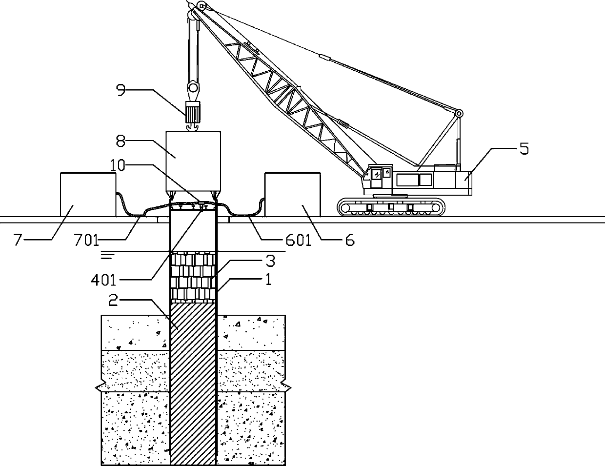
[0050] On the basis of Embodiment 1, the air supply pipe 601 and the liquid supply pipe 701 are connected to the gas-liquid inlet pipe 401 through a three-way 10, and the three-way 10 adopts an L-shaped three-way regulating valve.

Embodiment 3

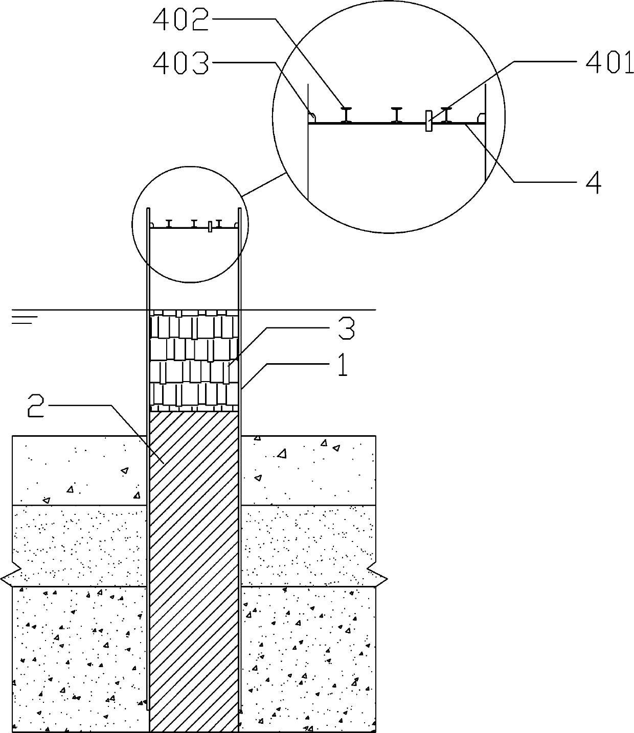
[0052] Such as figure 2 , on the basis of Example 1, in step 2), after the capping steel plate 4 is welded, a plurality of parallel stiffening steels 402 are welded on the top surface of the capping steel plate 4, and at the same time, on the top surface of the capping steel plate 4 and the steel guard A plurality of stiffening plates 403 are welded at equal angles between the inner walls of the barrel 1 .

[0053] The present invention adopts the above-mentioned method of "mud plugging + gas-liquid jacking combination + vibrating hammer weight", which can effectively improve the safety and stability in the construction process of removing the steel casing and ensure the smooth progress of the pulling operation of the steel casing. The extraction of steel casing under stratum conditions provides an effective means.


PUM


Abstract

The invention relates to a steel casing pulling-removal method which comprises the following steps of (1) adopting impermeable soil for backfilling, and preparing a mud slurry for plugging a formation; (2) full-length welding a capping steel plate at the upper end of a steel casing, and reserving a gas-liquid inlet pipe; (3) installing and moving equipment in: moving lifting equipment in, and installing a rotary motor and a vibration hammer, wherein the vibration hammer is connected with the steel casing; (4) liquifying a soil mass: starting the vibration hammer to liquify the soil mass aroundthe steel casing; (5) pressurizing through a hydraulic system: applying water pressure in the steel casing, slowly lifting the lifting equipment, and starting the rotary motor at the same time; (6) pressurizing through an air pressure system: applying air pressure into the steel casing, and continuously lifting the steel casing; and (7) pressurizing through a hydraulic system: when the steel casing is 3 to 5m away from a pile block, stopping air feeding, releasing pressure, starting the hydraulic system to apply water pressure into the steel casing, and then pulling out of a pile body. By adopting the method, through a gas-liquid pressurization combination method, the difficulty in pulling and removing the steel casing under a special condition in the prior art is saved, and the safety and the stability in the steel casing pulling-removal process are effectively ensured.

Description

technical field [0001] The invention relates to the construction field of cast-in-situ piles, in particular to a method for pulling out steel casings for special formations. Background technique [0002] The super-long steel casing is often used as the enclosure structure for bored piles, and the vibration hammering method is often used for sinking the steel casing. For the removal of the steel casing, the removal needs to overcome the self-weight of the steel casing and the frictional resistance of the formation. Large-scale lifting equipment is often used to pull it out. tearing, the casing cannot be pulled out, and this method is not applicable to the limited use of large equipment; the air pressure jacking method, after the casing is capped, no air pressure is added to the casing, and the air pressure is used to overcome the self-weight of the casing and formation friction resistance, the casing is pulled out of the formation, but the air pressure control is more compli...

Claims


Application Information

Patent Timeline
Patent Type & Authority Applications(China)
IPC IPC(8): E02D9/02
CPCE02D9/02
Inventor 刘宁波张成林朱虎张俊光张少博戴威颜松陈国海张涛臣张波黄斌别亚威陈丹文敬华
Owner CCCC SECOND HARBOR ENG
Why Eureka
Try Eureka