Centering device and method for reinforced cage of bored pile
A technology of centering device and steel cage, which is applied to the test of sheet pile walls, buildings, and foundation structures, etc., can solve the problems of affecting the centering accuracy, the wrong drop of the hand-held pendant, and the long distance, so as to improve the centering accuracy, The effect of avoiding detection errors
- Summary
- Abstract
- Description
- Claims
- Application Information
AI Technical Summary
Problems solved by technology
Method used
Image
Examples
Embodiment 1
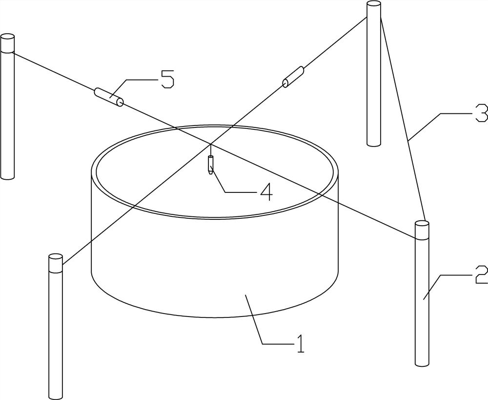
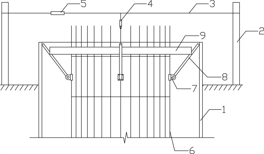
[0040] Such as Figure 1-2 Among them, a reinforcement cage centering device for bored piles, including two sets of guard piles 2 arranged on the ground around the pile hole and a centering disc 11 arranged on the reinforcement cage 6, the single set of guard piles 2 includes Two protective piles 2, the connecting line between the two protective piles 2 in the same group passes through the center of the pile hole, the first pair of centering ropes 3 are arranged on the two groups of protective piles 2, and the first pair of centering ropes 3 bypass The guard piles 2 are arranged in a cross shape, and a laser emitter 4 facing downward is tied to the intersection point;
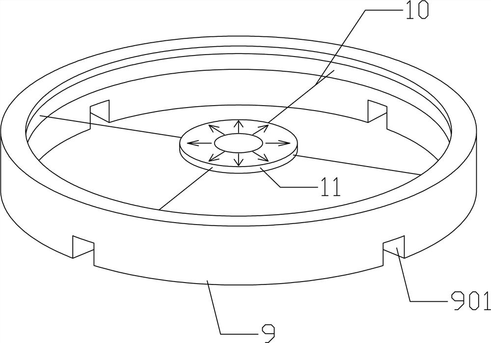
[0041] A centering plate 11 is provided at the center of the inner circle of the reinforcing cage 6 , and a centering qualified area 111 is printed on the center of the centering plate 11 .
[0042] In a preferred solution, one end of the first pair of centering ropes 3 is fixed on one of the guard piles 2 in ...
Embodiment 2
[0044] Such as Figure 5 , On the basis of Embodiment 1, the first centering rope 3 is provided with a centering rope tensioning device 5 .
[0045] In a preferred solution, the centering rope tensioning device 5 adopts a hollow cylindrical structure, and the two ends of the centering rope tensioning device 5 have holes, and the first centering rope 3 forms a breakpoint at the position of the centering rope tensioning device 5 , the breakpoint position of the first centering rope 3 connected to the centering rope tensioning device 5 passes through the end hole of the centering rope tensioning device 5 and extends into the inner chamber 501 of the centering rope tensioning device 5;
[0046] The inner cavity 501 is provided with a movable plate 13 capable of sliding in the centering rope tensioning device 5, and a tension spring 14 is arranged between the movable plate 13 and the inner wall of one end of the inner cavity 501;
[0047] Knots 301 are provided on the breakpoints ...
Embodiment 3
[0049] Such as figure 2 , 6 , On the basis of Embodiment 1, at least three fixed blocks 7 are arranged at equal angles on the same horizontal plane outside the steel cage 6, and the fixed blocks 7 are hingedly connected to one end of the movable rod 8.
[0050] In a preferred solution, one end of the fixed block 7 is provided with a through hole 701 for the main reinforcement of the reinforcement cage 6 to pass through, and the other end is provided with an ear plate 702 , and the end of the movable rod 8 is hinged on the ear plate 702 .
PUM
 Abstract
Description
Claims
Application Information
 - R&D Engineer
- R&D Manager
- IP Professional
- Industry Leading Data Capabilities
- Powerful AI technology
- Patent DNA Extraction
Browse by: Latest US Patents, China's latest patents, Technical Efficacy Thesaurus, Application Domain, Technology Topic, Popular Technical Reports.
© 2024 PatSnap. All rights reserved.Legal|Privacy policy|Modern Slavery Act Transparency Statement|Sitemap|About US| Contact US: help@patsnap.com


