
Calibration method and device for relative spatial position relation of multiple robots

A multi-robot, relative space technology, applied in manipulators, program-controlled manipulators, manufacturing tools, etc., can solve problems such as rising costs, unfavorable engineering operations, and exceeding the measurement range of 3D sensors, so as to eliminate calibration errors, improve universality, The effect of reducing the amount of calculation

Pending Publication Date: 2020-07-28
ASIMCO INT CASTING CO LTD SHANXI
View PDF7 Cites 5 Cited by
  • Summary
  • Abstract
  • Description
  • Claims
  • Application Information

AI Technical Summary

Problems solved by technology

[0005] (2) When the distance between robots is quite large, this calibration method may exceed the measurement range of the 3D sensor and cannot complete the calibration task
[0006] (3) This calibration method needs to make multiple calibration objects. As the number of robots to be calibrated increases, standard calibration objects need to be added simultaneously. The production cycle of standard calibration objects is relatively long, and it will also lead to an increase in cost, so it is not conducive to actual engineering. operate
[0007] (4) In the actual calibration, in order to carry the 3D sensor to take pictures of the calibration object in different attitudes, the robot needs to have a rotation change on each axis of the end coordinate system to ensure that the calibration object is within the field of view of the sensor. Therefore, it is very difficult for non-6-axis robots to operate. Difficult, basically unable to complete the calibration work

Method used


Image

  • Calibration method and device for relative spatial position relation of multiple robots
  • Calibration method and device for relative spatial position relation of multiple robots
  • Calibration method and device for relative spatial position relation of multiple robots

Examples


Embodiment Construction

[0039] In order to better explain the present invention and facilitate understanding, the present invention will be described in detail below through specific embodiments in conjunction with the accompanying drawings.

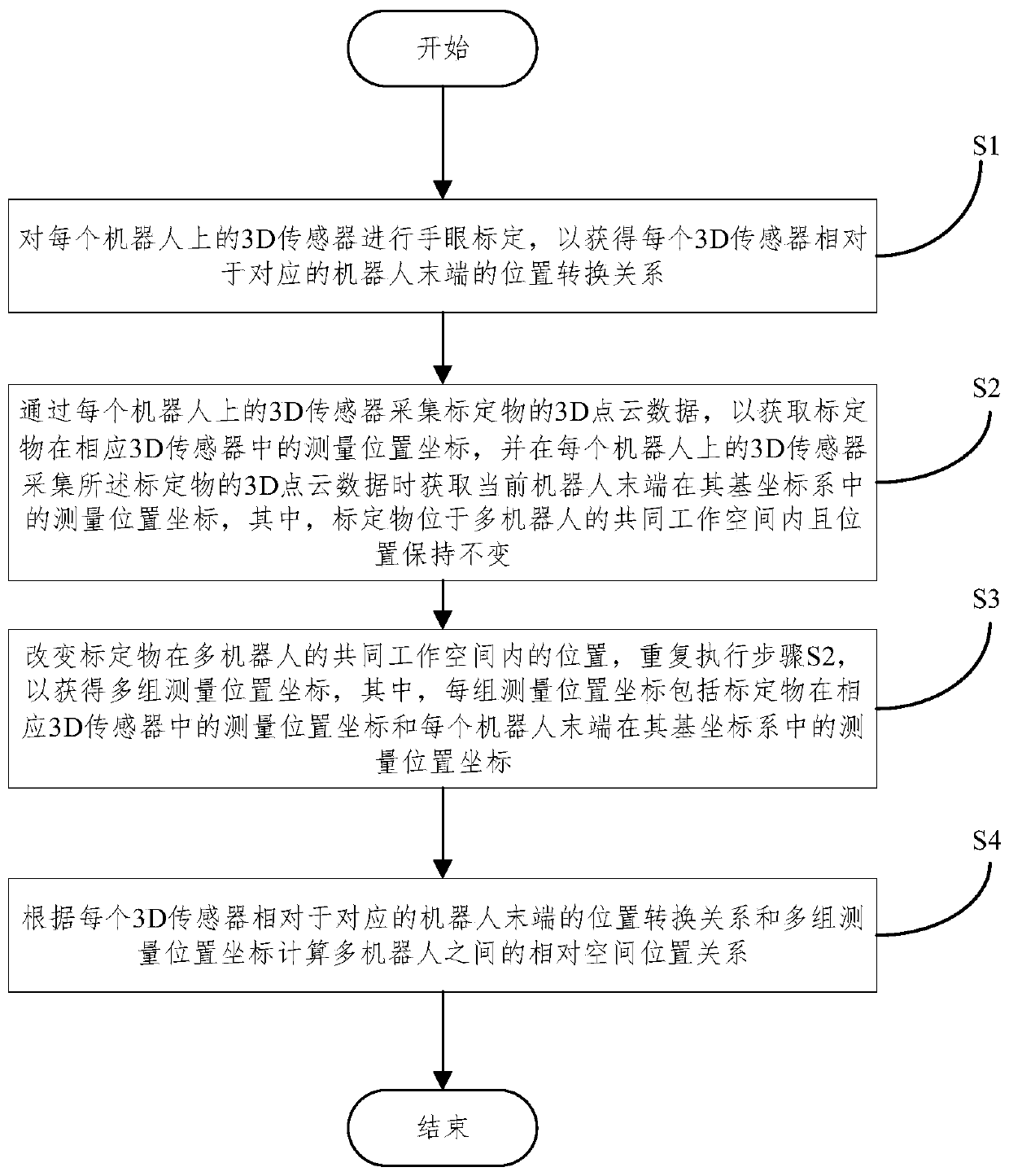
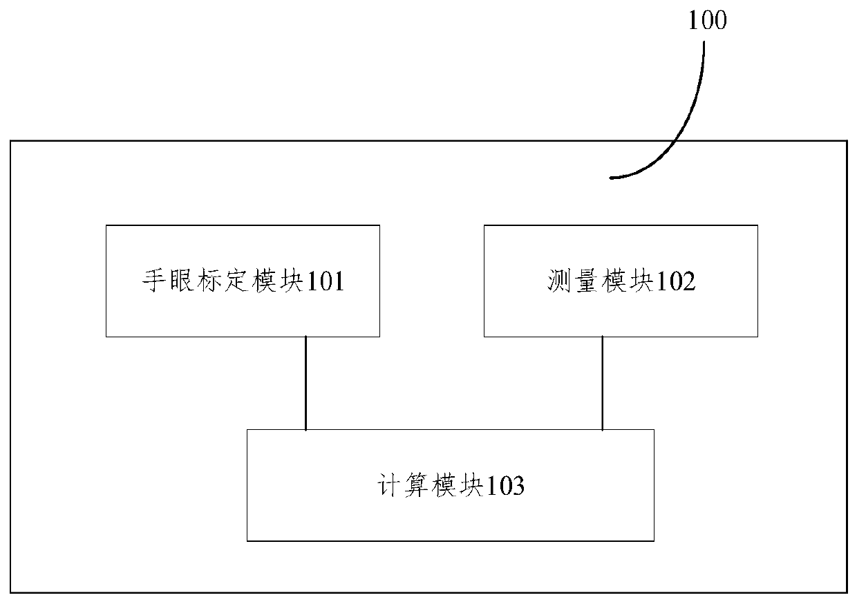
[0040] The calibration method and calibration device for the relative spatial position relationship of multiple robots proposed in the embodiments of the present invention make full use of the 3D sensors at the end of each robot, and perform hand-eye calibration on the 3D sensors on each robot to obtain the relative spatial position of each 3D sensor. The position conversion relationship of the corresponding robot end, and collect the 3D point cloud data of the calibration object placed in the multi-robot co-working space through the 3D sensor on each robot to obtain the measurement position coordinates of the calibration object in the corresponding 3D sensor At the same time, when the 3D sensor on each robot collects the 3D point cloud data of the calibration o...


PUM


Abstract

The invention relates to a calibration method and device for a relative spatial position relation of multiple robots. The calibration method comprises the steps that hand-eye calibration is conductedon 3D sensors on all the robots to obtain the position conversion relation of each 3D sensor relative to the tail end of the corresponding robot, 3D point cloud data of a calibration object placed ina common working space of the multiple robots are collected through the 3D sensors on all the robots to obtain measurement position coordinates of the calibration object in the corresponding 3D sensors, and meanwhile the measurement position coordinates of the tail end of the current robot in a base coordinate system of the robot are obtained when the 3D sensors on all the robots collect the 3D point cloud data of the calibration object. In the abovementioned way, by changing the position of the calibration object in the common working space of the multiple robots, multiple sets of measurementposition coordinates are obtained, the relative spatial position relation between the multiple robots is calculated according to the position conversion relation of each 3D sensor relative to the tail end of the corresponding robot and the multiple sets of measurement position coordinates, and accurate calibration of the spatial position relation of the multiple robots is achieved.

Description

technical field [0001] The present invention relates to the technical field of industrial robots, in particular to a method for calibrating the relative spatial position relationship of multiple robots, a computer-readable storage medium, a calibration device for the relative spatial position relationship of multiple robots, and a multi-robot system. Background technique [0002] The application of industrial robots continues to expand to various industries. In some applications, the size of the workpiece needs to be calculated, or other tasks need to be completed collaboratively, and the size of the workpiece may be quite large or the working space of the robot is quite large. For example, the size of the workpiece reaches 10m*3m* 1m, currently there is no corresponding visual device that can shoot such a large visual range. At this time, each robot end is generally equipped with a visual sensor, and each visual sensor captures a part of the workpiece. Through the relative ...

Claims


Application Information

Patent Timeline
IPC IPC(8): B25J9/16B25J13/08
CPCB25J9/1682B25J13/088Y02P90/02
Inventor 袁明王金文
Owner ASIMCO INT CASTING CO LTD SHANXI
Learn More