
A high-precision workpiece component and an assembly method of the high-precision workpiece component

An assembly method and high-precision technology, applied in the field of assembly of high-precision workpiece components and high-precision workpiece components, can solve problems such as prolonging the assembly cycle, affecting production efficiency, reducing yield, etc., achieving simple and clear principles, optimizing the assembly process, The effect of reducing production costs

Active Publication Date: 2021-08-24
CHONGQING UNIV
View PDF0 Cites 0 Cited by
  • Summary
  • Abstract
  • Description
  • Claims
  • Application Information

AI Technical Summary

Problems solved by technology

[0002] In modern industrial production, the assembly process of most workpiece components is completed by robotic arms. Among them, when it comes to the assembly of high-precision workpiece components, the disadvantage of low precision of the visual positioning method often occurs that the positioning of the workpiece components is not accurate and the robot cannot be accurate. Clamping the workpiece components makes it impossible to complete the assembly of subsequent workpiece components, thereby reducing the stability of the assembly system, reducing the yield rate, and affecting production efficiency; and when the computer is assembling high-precision workpiece components, the computer also calibrates the assembly position multiple times. However, it is still impossible to complete the assembly of workpiece components, and even cause the computer to crash and cause the assembly process to stall, prolonging the assembly cycle

Method used


Image

  • A high-precision workpiece component and an assembly method of the high-precision workpiece component
  • A high-precision workpiece component and an assembly method of the high-precision workpiece component
  • A high-precision workpiece component and an assembly method of the high-precision workpiece component

Examples


Embodiment Construction

[0097] The specific implementation manner and working principle of the present invention will be further described in detail below in conjunction with the accompanying drawings.

[0098] In this example, W 1 =15,W 2 = 10mm, W 3 = 4mm, W 4 =100.

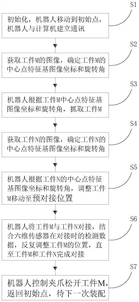
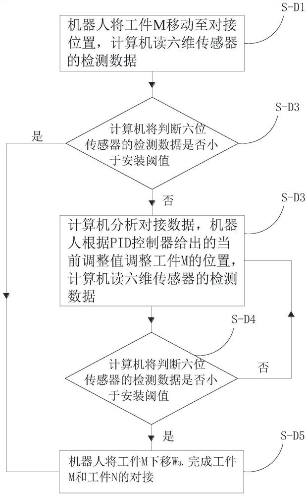
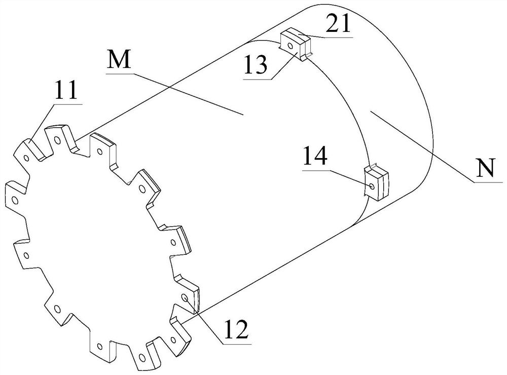
[0099] from figure 1 It can be seen that an assembly method of a high-precision workpiece assembly includes a workpiece assembly, the workpiece assembly includes a workpiece M and a workpiece N, and the workpiece M and workpiece N are assembled according to the following steps:

[0100] Preprocessing: place the workpiece M on the tooling to be grasped, and place the workpiece N on the docking tooling; install the image collector and the six-dimensional sensor on the robot, and set the image collector to take pictures of the workpiece M and workpiece N respectively point; set the alignment position and grasping position of the robot jaws to the workpiece M in the computer, set the pre-docking position and docking position of the w...


PUM


Abstract

The invention discloses a high-precision workpiece component and an assembly method of the high-precision workpiece component. A robot drives an image collector to respectively collect images of the workpiece component, and the image collected by the computer image collector performs precise positioning on the workpiece component, and the robot realizes the Grab and assemble the workpiece components; in the assembly of the workpiece components, the computer accurately and steadily controls the robot to repeatedly adjust the relative position between the workpiece components through the PID controller according to the data detected by the six-dimensional sensor until the workpiece components are assembled; the robot The assembly operation of the workpiece components is automatically controlled by the computer to make the assembly more intelligent; through the PID controller to control the robot, the assembly process of the workpiece components can be made more stable and more accurate, and the PID control principle is simple and clear, and the computer calculation speed is fast. Adjust the parameters of the PID controller according to the historical docking data, optimize the assembly process of workpiece components, reduce production costs and improve production efficiency.

Description

technical field [0001] The invention relates to the technical field of assembling high-precision workpiece components, in particular to a high-precision workpiece component and a method for assembling the high-precision workpiece component. Background technique [0002] In modern industrial production, the assembly process of most workpiece components is completed by robotic arms. Among them, when it comes to the assembly of high-precision workpiece components, the disadvantage of low precision of the visual positioning method often occurs that the positioning of the workpiece components is inaccurate and the robot cannot be accurate. Clamping the workpiece components, so it is impossible to complete the assembly of subsequent workpiece components, thereby reducing the stability of the assembly system, reducing the yield rate, and affecting production efficiency; and when the computer is assembling high-precision workpiece components, the computer also calibrates the assembly...

Claims


Application Information

Patent Timeline
Patent Type & Authority Patents(China)
IPC IPC(8): B25J9/16B25J13/08B25J15/08G06K9/00G06K9/32G06K9/46G06K9/34
CPCB25J9/1602B25J9/1697B25J13/087B25J15/08G06V20/10G06V10/25G06V10/267G06V10/56
Inventor 欧阳奇曹晨光侯佳木王媛媛杜凌霄李继祥金留欢柳刚刘旭阳
Owner CHONGQING UNIV
Learn More