Auxiliary fixing device used for model making

A technology of fixing devices and models, which is applied to the devices for coating liquid on the surface, manufacturing tools, and parts of grinding machine tools, etc., which can solve the problems of inconvenient operation, low processing efficiency, and difficulty in quickly adjusting the inclination angle of parts to achieve fast Adjustment effect

Inactive Publication Date: 2020-07-28
刘斌
View PDF7 Cites 4 Cited by
  • Summary
  • Abstract
  • Description
  • Claims
  • Application Information

AI Technical Summary

Problems solved by technology

[0003] When making a model, it is often necessary to fix the manufactured parts, and then add glue to the upper end of the parts or polish them. The current auxiliary fixing devices are generally simple in structure and can only fix simple parts. When processing, it is often necessary to remove the parts or squat artificially for processing, which is inconvenient to operate. The existing auxiliary fixing device is not easy to quickly adjust the inclination angle of the parts, resulting in low processing efficiency

Method used


Image

  • Auxiliary fixing device used for model making
  • Auxiliary fixing device used for model making
  • Auxiliary fixing device used for model making

Examples


Embodiment 1

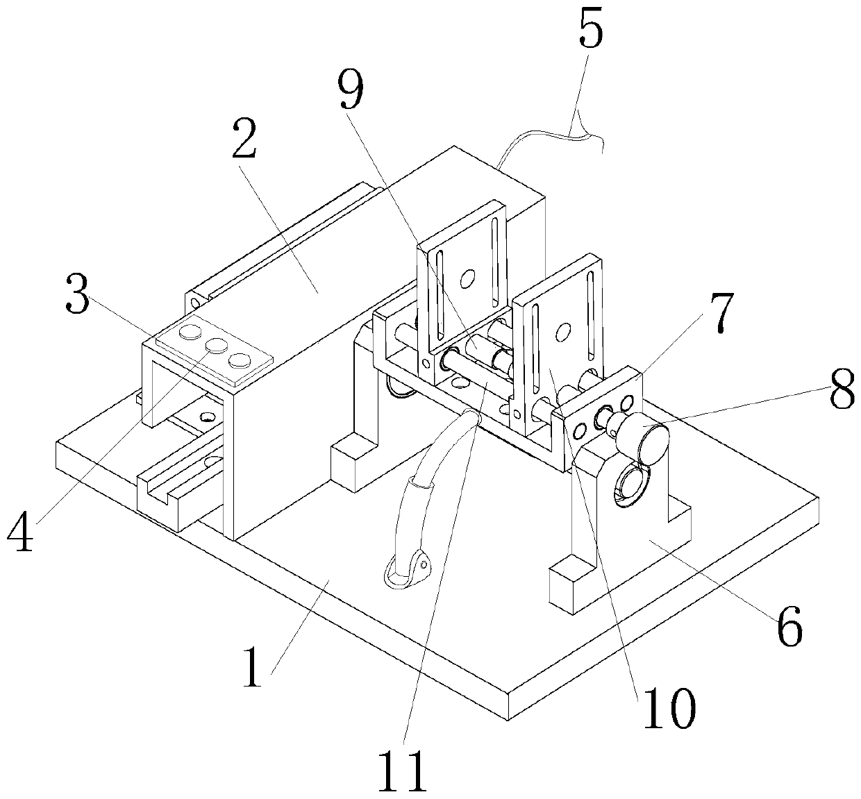
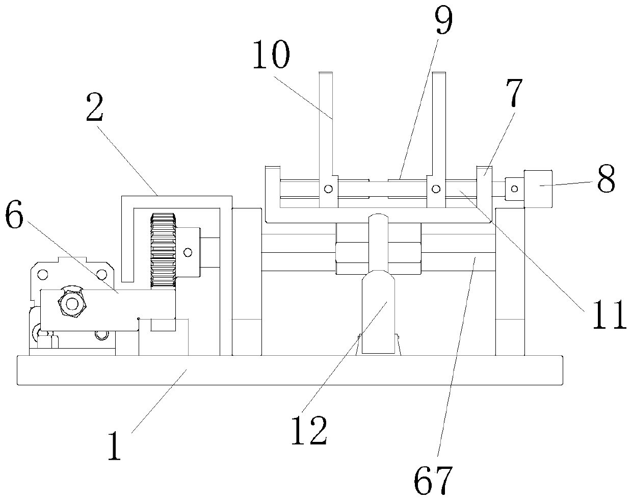
[0028] see figure 1 and figure 2 , the present invention provides an auxiliary fixing device for model making through improvement, including a bottom plate 1, a fixing seat 7, a knob 8, a screw rod 9, a splint 10, a slide bar 11, a tilting mechanism 6 and a buffer mechanism 12, The bottom plate 1 and the bottom of the protective cover 2 are fixed together, the top of the protective cover 2 is provided with a control panel 3, the top of the control panel 3 is equipped with a button 4, the rear end of the protective cover 2 is fixed with a power lead 5, and the screw rod 9 is connected to the inner wall of the fixing seat 7 Flexible connection, the tilting and turning mechanism 6 is installed and fixed on the inner side of the protective cover 2, and the tilting and turning mechanism 6 is tightly fixed to the bottom of the fixing seat 7, the buffer mechanism 12 is fixedly connected to the front end of the fixing seat 7, the screw rod 9 is fixedly connected to the left end of th...

Embodiment 2

[0032] The present invention provides an auxiliary fixing device for model making through improvement. There are two splints 10 in total, and the splints 10 are symmetrically distributed along the left and right sides of the upper end of the screw rod 9, which is beneficial to clamping the parts. For the function of fixing, the upper end of the screw rod 9 is provided with threads, and the left and right ends of the upper end of the screw rod 9 are symmetrical threads, which is beneficial to drive the two splints 10 to clamp the parts, and the upper end of the knob 8 is provided with strip-shaped anti-skid lines , and the anti-slip lines are equidistantly distributed along the surface of the upper end of the knob 8, which is beneficial to play the role of anti-slip.

[0033] The present invention provides an auxiliary fixing device for model making through improvement, and its working principle is as follows;

[0034] First, before use, the auxiliary fixing device used for mod...


PUM


Abstract

The invention discloses an auxiliary fixing device used for model making. The auxiliary fixing device comprises a bottom plate, a fixed seat, a rotary knob, a lead screw, a clamping plate, a sliding rod, an inclined overturning mechanism and buffering mechanisms. The inclined overturning mechanism is arranged at the upper end of the bottom plate, an electric push rod is powered on to work, a fixedplate drives a sliding seat to move at the upper end of a guide rail, the sliding seat drives a gear to rotate through a rack, and a rotating shaft drives the fixed seat to rotate, so that the inclination position of a part is changed, and the advantage of quickly adjusting the inclination angle of the part is achieved; the buffering mechanisms are arranged at the front end and the rear end of the fixed seat, when the fixed seat inclines, a pressing rod can be driven to move on the inner side of a stand column, the pressing rod drives a buffering spring to deform, and therefore the fixed seatinclines stably, and the advantage that the fixed seat can be adjusted stably is achieved.

Description

technical field [0001] The invention relates to the related field of model making, in particular to an auxiliary fixing device for model making. Background technique [0002] Industrial model, commonly known as hand model, hand model and rapid prototyping, is widely used in the design and development stage of new industrial products. It can process the physical model consistent with the design in the shortest time, so as to reduce the development cost, shorten the development cycle, and quickly obtain customers. approved purpose. [0003] When making a model, it is often necessary to fix the manufactured parts, and then add glue to the upper end of the parts or polish them. The current auxiliary fixing devices are generally simple in structure and can only fix simple parts. When processing, it is often necessary to remove the parts or squat down artificially for processing, which is inconvenient to operate. The existing auxiliary fixing device is not easy to quickly adjust ...

Claims


Application Information

Patent Timeline
IPC IPC(8): B24B41/06B24B41/00B05C13/02
CPCB05C13/02B24B41/007B24B41/06
Inventor 刘斌
Owner 刘斌
Why Eureka
Try Eureka