
Polishing head and polishing device

A polishing head and driving device technology, applied in the direction of the work carrier, etc., can solve the problems of poor uniformity of the film-forming pattern and the like

Inactive Publication Date: 2020-07-28
INST OF MICROELECTRONICS CHINESE ACAD OF SCI +1
View PDF6 Cites 2 Cited by
  • Summary
  • Abstract
  • Description
  • Claims
  • Application Information

AI Technical Summary

Problems solved by technology

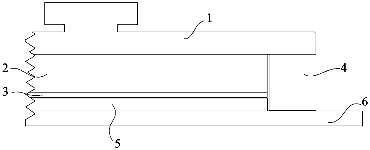
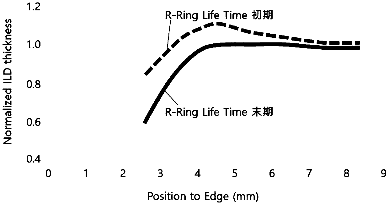
It can be seen that the film-forming pattern at the edge of the wafer 5 is significantly thinner than the film-forming pattern near the middle of the wafer 5, and the uniformity of the film-forming pattern on the wafer 5 is poor

Method used


Image

  • Polishing head and polishing device
  • Polishing head and polishing device
  • Polishing head and polishing device

Examples


Embodiment Construction

[0023] In order to make the purpose, technical solutions and advantages of the embodiments of the present invention clearer, the technical solutions in the embodiments of the present invention will be clearly and completely described below in conjunction with the drawings in the embodiments of the present invention. Obviously, the described embodiments It is only some embodiments of the present invention, but not all embodiments. Based on the embodiments of the present invention, all other embodiments obtained by persons of ordinary skill in the art without making creative efforts belong to the protection scope of the present invention.

[0024] In order to facilitate the understanding of the polishing head provided by the embodiment of the present invention, the application scene of the polishing head provided by the embodiment of the present invention is firstly described below. Keep the wafer on the polishing platform. The polishing head will be described in detail below i...


PUM


Abstract

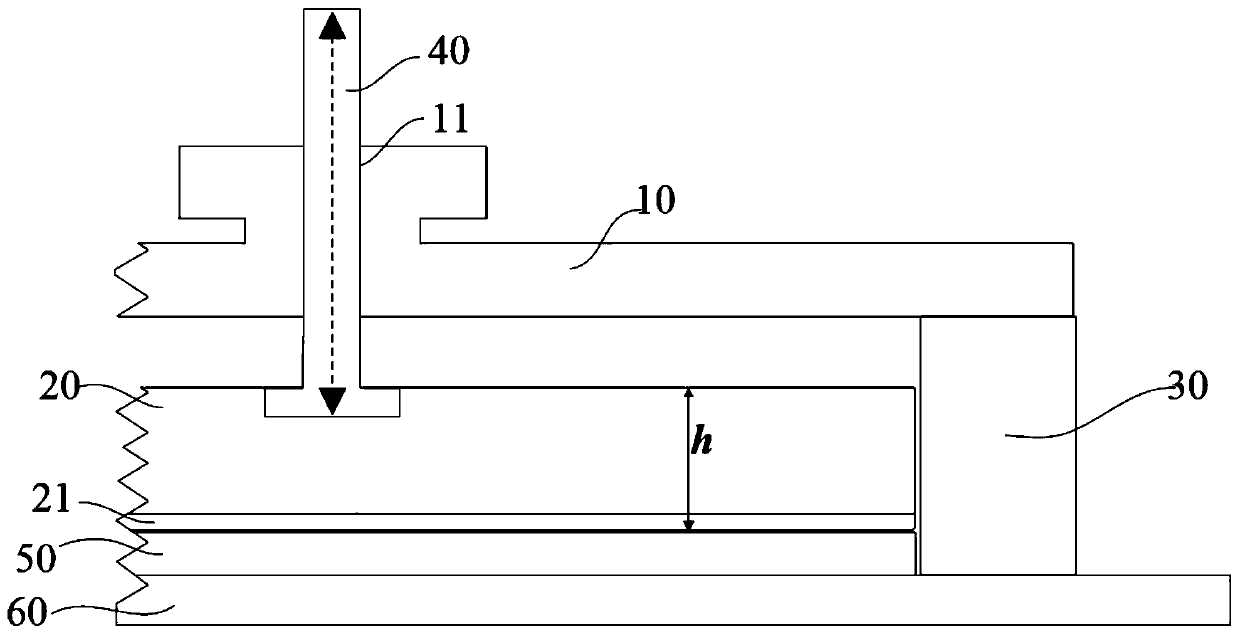
The invention provides a polishing head and a polishing device. The polishing head is used for keeping a wafer on a polishing platform. The polishing head comprises a shell and a limiting ring connected to the shell. The limiting ring surrounds the wafer to limit the wafer. The polishing head further comprises a bracket located in the limiting ring. A back film leaning against the surface of the wafer is arranged on the bracket. The bracket is slidably assembled on the shell along a first direction. The polishing head further comprises a driving device which drives the bracket to slide relative to the shell along the first direction. By way of slidably assembling the bracket on the shell along a direction parallel to the axis of the limiting ring and arranging the driving device to drive the bracket to slide along the axis direction of the limiting ring relative to the shell, the bracket can be driven by the driving device to move along a direction far away from the wafer when the limiting ring is relatively worn severely and the separation distance between the bracket and the surface of the wafer is kept in a reasonable range, so that the separation distance between the wafer andthe bracket is not reduced as a result of wear of the limiting ring, and therefore, the edge of the wafer is prevented from being polished excessively.

Description

technical field [0001] The invention relates to the technical field of semiconductor manufacturing, in particular to a polishing head and a polishing device. Background technique [0002] At present, as the patterns designed and produced on the wafer are gradually refined, the CMP (Chemical Mechanical Polishing, chemical mechanical polishing) process is increasing for various purposes. Therefore, the uniformity of the film formation pattern on the wafer in the CMP process becomes more important. The uniformity of the film formation pattern on the wafer in the CMP process is affected by the structure of the equipment, the mode, and the overall process. In order to improve the uniformity of the film pattern on the wafer, various methods such as Membrane Zone Control of the Polishing Head and Pad Conditioning Tuning are used. [0003] A chemical mechanical polishing device (CMP Polisher) is roughly composed of a polishing pad (Polishing Pad), a polishing head (Polishing Head)...

Claims


Application Information

Patent Timeline
IPC IPC(8): B24B37/30
CPCB24B37/30
Inventor 丁彦荣张月杨涛卢一泓刘青
Owner INST OF MICROELECTRONICS CHINESE ACAD OF SCI
Learn More