
Rigid-flex board for suit and manufacturing method

A technology of rigid-flex board and manufacturing method, which is applied in the structural connection of printed circuits, the manufacture of printed circuits, and the processing of insulating substrates/layers, etc., can solve the problem of unreasonable design of connection positions, complicated procedures, and high cost of cutting connection positions. problems, to avoid carbonization and blackening of the shape, simplify the sub-board process, and improve the efficiency and quality of the sub-board

Active Publication Date: 2021-10-08
SHENZHEN KINWONG ELECTRONICS
View PDF6 Cites 0 Cited by
  • Summary
  • Abstract
  • Description
  • Claims
  • Application Information

AI Technical Summary

Problems solved by technology

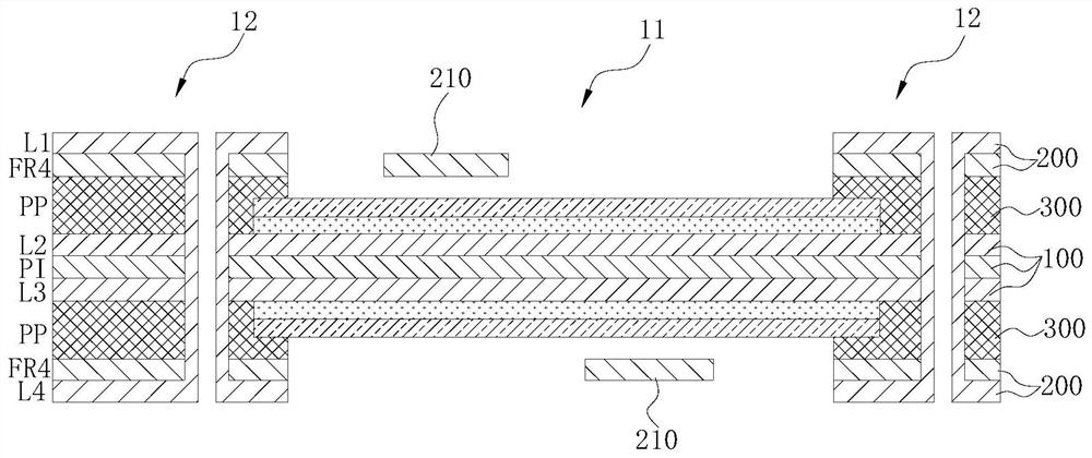
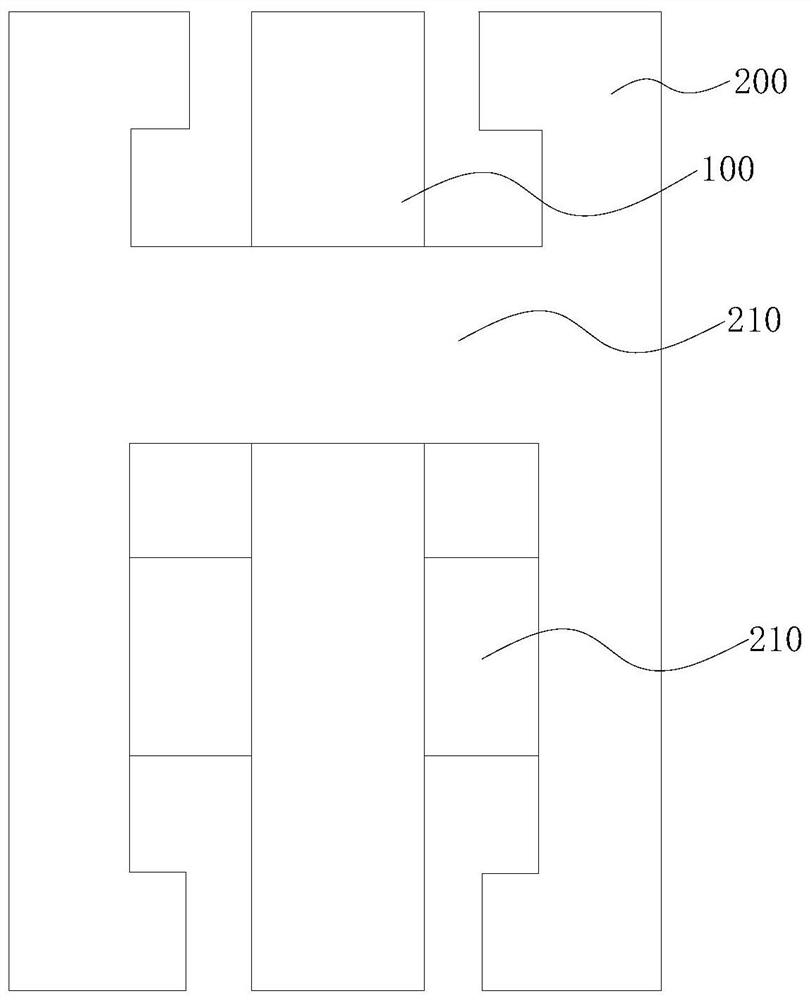
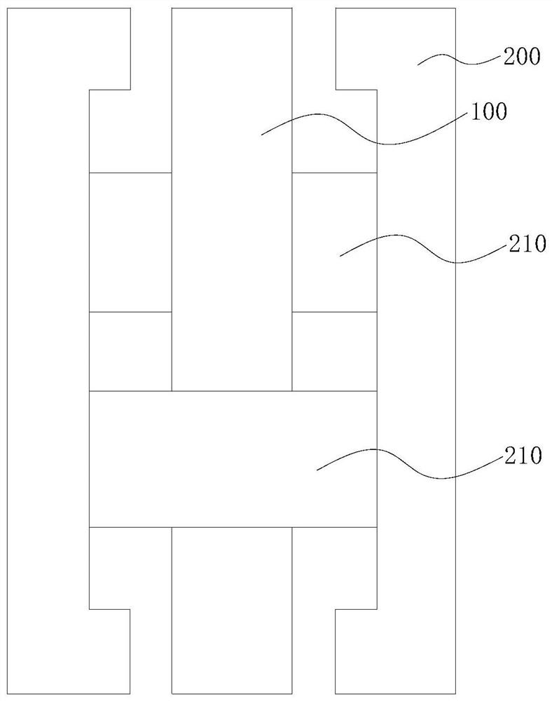
[0003] The purpose of the embodiments of the present application is to provide a rigid-flexible board for assembly, so as to solve the technical problems in the prior art that due to the unreasonable design of the connection position of the rigid-flexible board, the high cost and complicated process of cutting the connection position later

Method used


Image

  • Rigid-flex board for suit and manufacturing method
  • Rigid-flex board for suit and manufacturing method
  • Rigid-flex board for suit and manufacturing method

Examples


Embodiment Construction

[0028] In order to make the technical problems, technical solutions and beneficial effects to be solved by the present application clearer, the present application will be further described in detail below in conjunction with the accompanying drawings and embodiments. It should be understood that the specific embodiments described here are only used to explain the present application, and are not intended to limit the present application.

[0029] It should be noted that when an element is referred to as being “fixed” or “disposed on” another element, it may be directly on the other element or be indirectly on the other element. When an element is referred to as being "connected to" another element, it can be directly connected to the other element or indirectly connected to the other element.

[0030] It is to be understood that the terms "length", "width", "top", "bottom", "front", "rear", "left", "right", "vertical", "horizontal", "top" , "bottom", "inner", "outer" and oth...


PUM


Abstract

The application provides a rigid-flex board for suiting and a manufacturing method thereof. The rigid-flex board for suiting includes a flexible layer, an adhesive layer and a rigid layer, and the rigid layer is connected to the flexible layer through the adhesive layer. On the upper and lower sides, the rigid-flexible plate is formed with a flexible area and a rigid-flexible area. Between the rigid-flexible areas on both sides, a plurality of rigid clamping joints are arranged at intervals. The clamping joints are integrally formed on the rigid layer. The clamping connection positions of the flexible regions on the upper and lower sides are dislocated, and each clamping connection position jointly forms a clamping support structure for clamping and supporting the flexible layer corresponding to the flexible region. In this application, the rigid connection position is set in the flexible area, which can avoid milling and cutting the flexible connection position when the board is divided. It only needs to use the mechanical milling method to divide the set rigid-flexible combination board into individual pieces. The process is less and the division is simplified. The board process is easy to operate and low in cost, avoiding the problem of carbonization and blackening of the shape caused by laser cutting flexible joints, and improving the efficiency and quality of board splitting.

Description

technical field [0001] The present application belongs to the technical field of circuit boards, and more specifically relates to a rigid-flexible combination board for packaging and a manufacturing method thereof. Background technique [0002] In order to improve the assembly efficiency, when the rigid-flex board is shipped to the component assembly factory, most of the cases are in the form of a set composed of several single pieces. The single piece and the rigid frame of the set are combined through the connection position. These connection positions are generally designed in Rigid area. However, when the flexible area is long, in order to prevent the flexible area from being bent and deformed, which will affect the operation, assembly and / or testing, it is necessary to design a connecting position in the flexible area to connect to the rigid casing frame. After the assembly of the components is completed, the assembly plant needs to divide the package board into indivi...

Claims


Application Information

Patent Timeline
Patent Type & Authority Patents(China)
IPC IPC(8): H05K1/02H05K1/14H05K3/00
CPCH05K1/0281H05K1/147H05K3/0052
Inventor 张志强周源伟王俊侯利娟焦阳
Owner SHENZHEN KINWONG ELECTRONICS
Learn More