
Single-feed double-circular-polarization directional antenna with extremely small frequency ratio and antenna system

A dual circularly polarized, directional antenna technology, applied in the antenna system, the extremely small frequency ratio of the single-fed dual circularly polarized directional antenna field, can solve the problems of increased antenna thickness, narrowed antenna frequency band, and decreased antenna radiation capability, etc. To achieve the effect of reducing the influence of the shape, reducing the quantity, and ensuring high performance

Active Publication Date: 2020-07-24
XIDIAN UNIV
View PDF11 Cites 0 Cited by
  • Summary
  • Abstract
  • Description
  • Claims
  • Application Information

AI Technical Summary

Problems solved by technology

[0005] (1) The existing method increases the thickness of the antenna, which destroys the inherent low-profile characteristics of the microstrip antenna, and it requires dual-port feeding
[0006] (2) Existing methods cannot achieve a minimum frequency ratio of 1.04
[0008] (1) Reducing the profile of the antenna will narrow the frequency band of the antenna, make it difficult to obtain dual-frequency characteristics, and increase the frequency ratio of the antenna; the antenna with single-port feed has a lower radiation ability than the antenna with dual-feed , it is not easy to achieve good performance
[0009] (2) There is no effective way to realize the extremely small frequency ratio of the dual-frequency circularly polarized microstrip antenna

Method used


Image

  • Single-feed double-circular-polarization directional antenna with extremely small frequency ratio and antenna system
  • Single-feed double-circular-polarization directional antenna with extremely small frequency ratio and antenna system
  • Single-feed double-circular-polarization directional antenna with extremely small frequency ratio and antenna system

Examples


Embodiment Construction

[0042] In order to make the object, technical solution and advantages of the present invention more clear, the present invention will be further described in detail below in conjunction with the examples. It should be understood that the specific embodiments described here are only used to explain the present invention, not to limit the present invention.

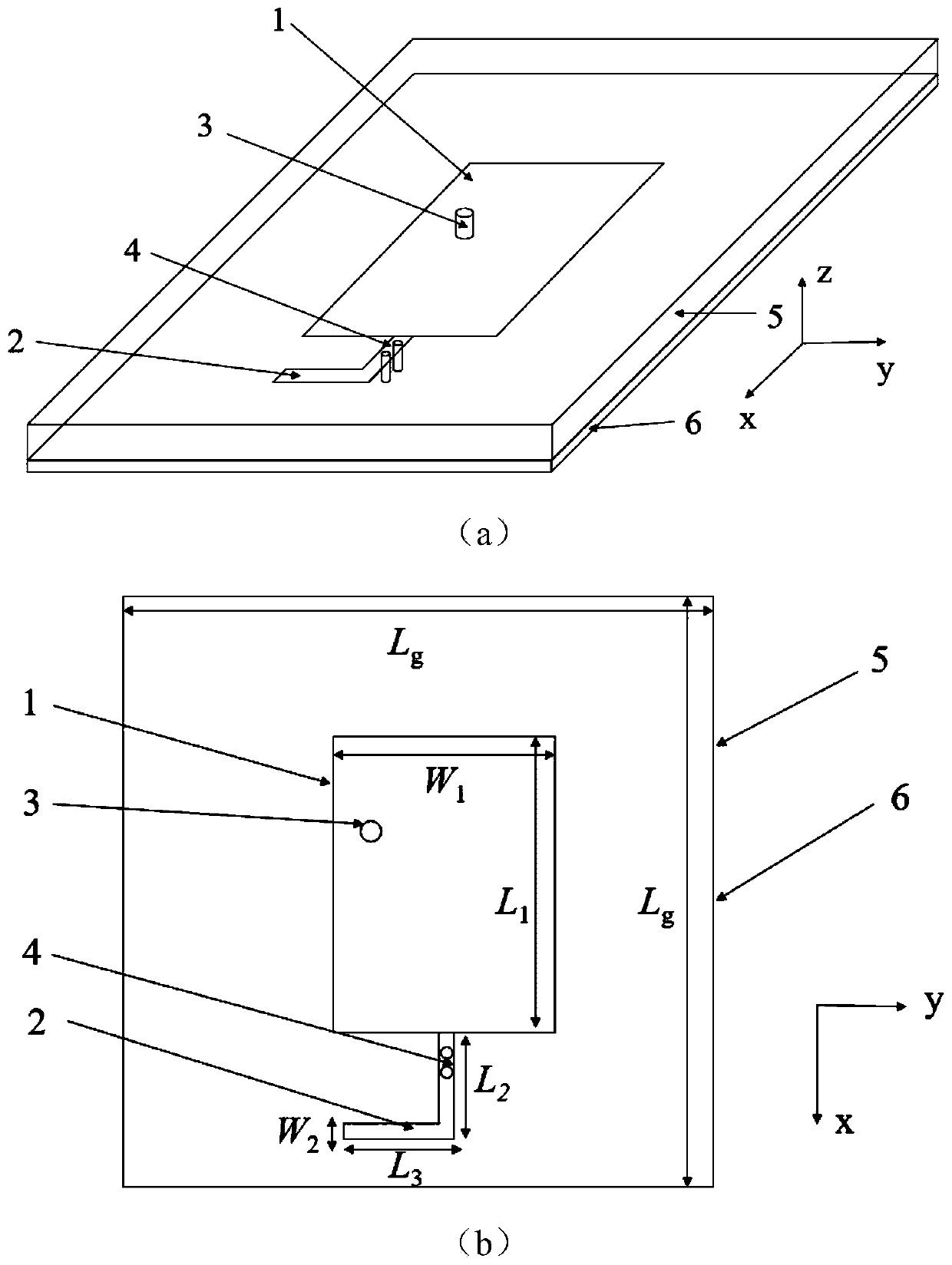
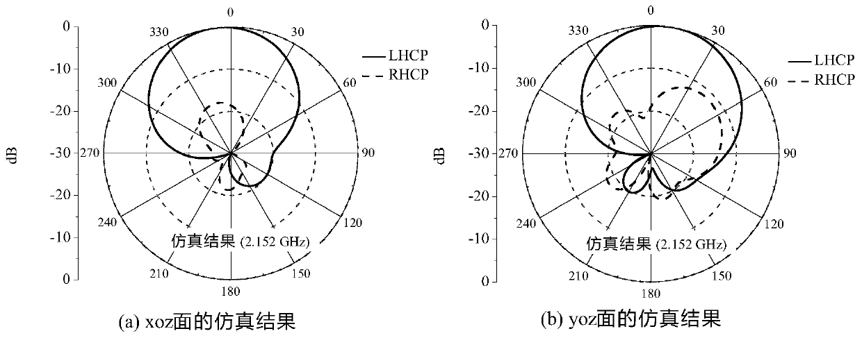
[0043] Aiming at the problems existing in the prior art, the present invention provides a single-feed dual circularly polarized directional antenna based on L-shaped stub loading with extremely small frequency ratio. The following is combined with the attached figure 1 to attach Figure 7 and Table 1 describe the present invention in detail.

[0044] Aiming at the problems of high antenna unit section, multi-port feeding and difficulty in realizing dual circular polarization directional radiation characteristics with extremely small frequency ratio in the existing mobile communication. The present invention adopts the met...


PUM


Abstract

The invention belongs to the technical field of antenna parts or devices combined with antennas, and discloses a single-feed double-circular-polarization directional antenna with an extremely small frequency ratio and an antenna system. The antenna is provided with a rectangular micro-strip, and the rectangular micro-strip is positioned on the uppermost layer of the antenna and is printed on a dielectric substrate by adopting a printed circuit process; a stub line is positioned on the uppermost layer of the antenna and is printed on the dielectric substrate through a printed circuit process; two metal through holes are formed above the stub line and are symmetrically formed along the center; the dielectric substrate is positioned on the middle layer of the antenna; and a metal bottom plateis located at the lower layer of the dielectric substrate, and the metal bottom plate is provided with a radio frequency connector. The requirement for achieving the dual-frequency dual-circular-polarization directional radiation characteristic with the extremely-small frequency ratio of a traditional low-profile micro-strip antenna under single feeding is met. While the high performance of the antenna is ensured, the influence of the antenna on the appearance of a carrier can be reduced to the greatest extent. The number of input ports is reduced, and the characteristic can be realized without switching different ports.

Description

technical field [0001] The invention belongs to the technical field of antenna components or devices combined with antennas, and in particular relates to a single-feed dual circularly polarized directional antenna and an antenna system with a very small frequency ratio. Background technique [0002] At present, in modern wireless communication systems, dual circularly polarized directional antennas (with both left-handed and right-handed circular polarization characteristics) have the advantages of working at multiple frequencies, avoiding polarization loss, and suppressing multipath scattering and multipath interference. More and more attention. The microstrip patch antenna has the advantages of low cost, light weight, and easy conformality, so the research on the dual-frequency circularly polarized microstrip antenna is imperative. [0003] However, the frequency ratio of traditional dual-band circularly polarized microstrip patch antennas, especially the orthogonally pol...

Claims


Application Information

Patent Timeline
Patent Type & Authority Applications(China)
IPC IPC(8): H01Q1/38H01Q1/50H01Q5/10H01Q5/307H01Q5/50
CPCH01Q1/38H01Q1/50H01Q5/10H01Q5/307H01Q5/50
Inventor 刘能武孙美娇傅光祝雷
Owner XIDIAN UNIV
Learn More