Wind turbine blade de-icing device and wind turbine

A technology for wind turbines and blades, which is applied to wind turbines, wind turbine control, and wind turbine monitoring, etc., can solve problems such as the inability to protect circuits immediately

Active Publication Date: 2021-10-29
SANY ELECTRIC CO LTD
View PDF10 Cites 0 Cited by
  • Summary
  • Abstract
  • Description
  • Claims
  • Application Information

AI Technical Summary

Problems solved by technology

[0005] The object of the present invention is to provide a blade deicing device for a wind power generating set and a wind generating set, so as to alleviate the possible overheating of the circuit between the power supply and the heating element during the use of the blade deicing device for a wind generating set in the prior art. In the case of over-current dry-burning, in order to protect the circuit, it is necessary to disconnect the circuit immediately when over-current dry-burning occurs. Wait for the temperature on the blades to rise gradually to a higher temperature, and then use the controller to cut off the power to the heating element to protect the circuit, but the technical problem that the circuit cannot be immediately protected when the circuit between the power supply and the heating element is over-current and dry-burned

Method used


Image

  • Wind turbine blade de-icing device and wind turbine
  • Wind turbine blade de-icing device and wind turbine

Examples


Embodiment 1

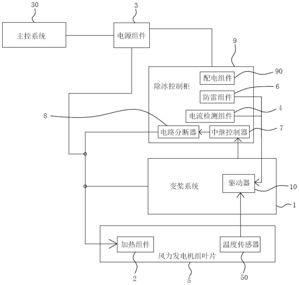
[0037] Such as figure 1 As shown, the wind power generator blade deicing device provided in this embodiment includes a pitch system 1 , a heating assembly 2 , a power supply assembly 3 and a current detection assembly 4 . The pitch system 1 is provided with a driver 10, and the power supply assembly 3, the driver 10 and the heating assembly 2 are connected in sequence. The current detection component 4 is installed on the circuit between the heating component 2 and the power supply component 3, and is connected with the driver 10, and the current detection component 4 is used for detecting the current value. A preset current value is set in the driver 10, and the driver 10 can receive the current value detected by the current detection component 4, and control the power off between the heating component 2 and the power supply component 3 when the current value is greater than the preset current value. The heating assembly 2 is connected to the blade 5 of the wind power genera...

Embodiment 2

[0074] The wind power generator set provided in this embodiment includes blades and the blade deicing device of the wind power generator set in Embodiment 1, and the heating assembly in the blade deicing device of the wind power generator set is connected to the blades.

[0075] The wind power generating set provided in this embodiment includes the wind power generating set blade deicing device in Embodiment 1, so the wind generating set provided in this embodiment and the wind generating set blade deicing device in Embodiment 1 can solve the same technical problem , to achieve the same technical effect.


PUM


Abstract

The invention provides a blade deicing device of a wind power generator set and a wind power generator set, and relates to the technical field of wind power generation. The blade deicing device of the wind power generating set includes a pitch system, a heating assembly, a power supply assembly and a current detection assembly. A driver is arranged in the pitch control system, and the power supply component, the driver and the heating component are connected in sequence. The current detection component is installed on the circuit between the heating component and the power supply component, and is connected with the driver. A preset current value is set in the driver, and the driver can control the power cut between the heating component and the power supply component when the current value detected by the current detection component is greater than the preset current value. The invention alleviates the need to wait for the blade to gradually rise to a higher temperature when the circuit between the power supply and the heating element in the blade deicing device of the wind power generating set in the prior art is dry-burned, and then uses the controller to turn off the heating element. It is a technical problem that the circuit cannot be protected immediately when the circuit is over-current and dry-burned.

Description

technical field [0001] The invention relates to the technical field of wind power generation, in particular to a blade deicing device for a wind power generator set and a wind power generator set. Background technique [0002] A wind turbine is a device that converts wind energy into electrical energy. The wind generator controls the torque of the wind rotor by the generator, and the pitch system controls the pitch angle of the blades to maintain the stable operation of the wind turbine under various wind conditions. Due to the harsh working environment of the fan, the blades of the fan are prone to ice accumulation. Therefore, in order to prevent the fan from malfunctioning or being damaged due to ice accumulation on the blades of the fan, it is usually necessary to use a heating device to de-ice the blades of the fan. [0003] An existing blade deicing device for a wind power generating set includes a blade and a generating set, and a heating element and a temperature sens...

Claims


Application Information

Patent Timeline
Patent Type & Authority Patents(China)
IPC IPC(8): F03D80/40F03D80/60F03D17/00F03D7/00F03D80/30
CPCF03D7/00F05B2270/328F03D17/00F03D80/30F03D80/40F03D80/60Y02E10/72
Inventor 徐琛武文龙
Owner SANY ELECTRIC CO LTD
Why Eureka
Try Eureka