
Positioning hole structure for fixed side tail lamp

A positioning hole, fixed side technology, applied in vehicle components, combustion engines, signal devices, etc., can solve problems such as poor matching, water leakage, easy burn-through, etc., to improve waterproof sealing performance, reduce gap surface difference, and reduce tolerance accumulation. Effect

Pending Publication Date: 2020-07-24
HANTENG AUTOMOBILE CO LTD
View PDF0 Cites 2 Cited by
  • Summary
  • Abstract
  • Description
  • Claims
  • Application Information

AI Technical Summary

Problems solved by technology

Car rear lights are divided into fixed side tail lights and movable side tail lights. The fixed side tail lights are usually adjusted and fixed through two positioning holes in the X direction and one positioning hole in the Y direction when installing. Above, the tail light seat plate and the side wall outer plate are connected by solder joints. After the fixed side tail light is installed, it is matched with the side wall outer plate. Due to the accumulation of tolerances, poor matching is likely to occur, and the sharp corner welding is not easy to achieve here. Welding, easy to burn through and cause water leakage risk

Method used


Image

  • Positioning hole structure for fixed side tail lamp
  • Positioning hole structure for fixed side tail lamp
  • Positioning hole structure for fixed side tail lamp

Examples


Embodiment Construction

[0016] The following will clearly and completely describe the technical solutions in the embodiments of the present invention with reference to the accompanying drawings in the embodiments of the present invention. Obviously, the described embodiments are only some, not all, embodiments of the present invention. Based on the embodiments of the present invention, all other embodiments obtained by persons of ordinary skill in the art without making creative efforts belong to the protection scope of the present invention.

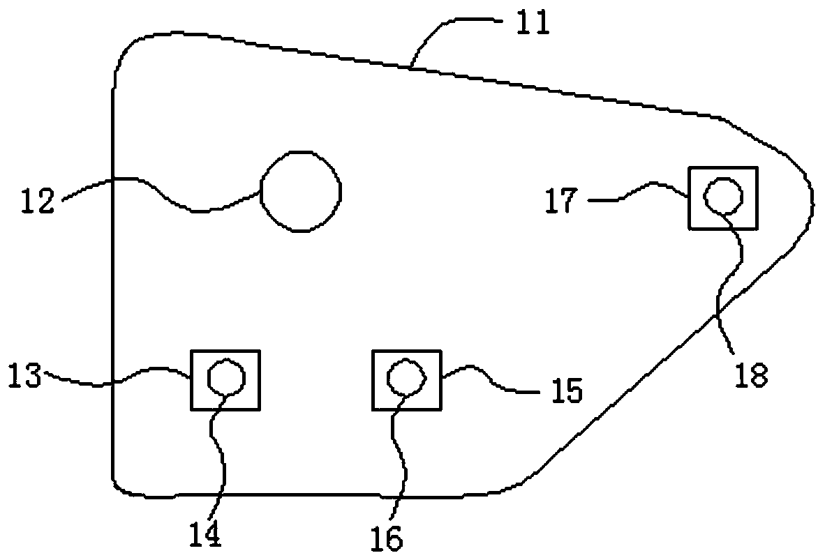
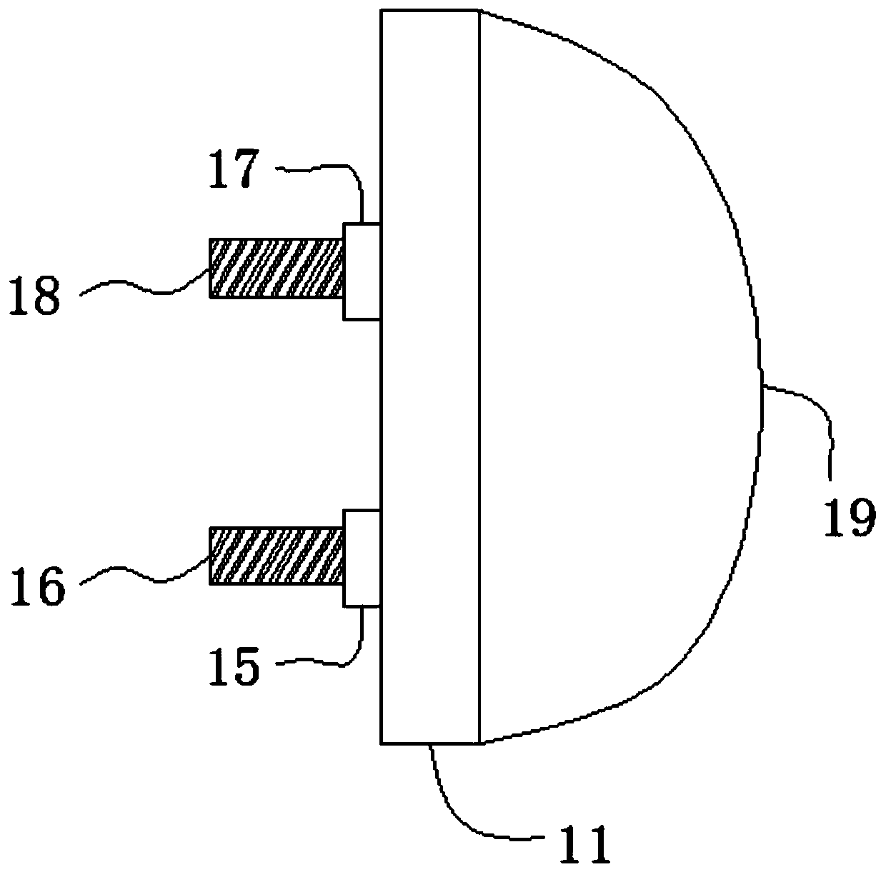
[0017] see Figure 1-3 , the present invention provides a technical solution: a fixed side tail light positioning hole structure, including a side wall outer panel 1, an installation groove 2 is arranged on the side wall outer panel 1, and a buckle 3 is fixedly installed on the bottom of the installation groove 2, The groove bottom of the installation groove 2 is provided with a wire hole 4, the groove bottom of the installation groove 2 is provided with a fir...


PUM


Abstract

The invention discloses a positioning hole structure for a fixed side tail lamp. The positioning hole structure comprises a side wall outer plate, a mounting groove is formed in the side wall outer plate, a Y-direction groove is formed in the bottom of the mounting groove, a Y-direction positioning hole is formed in the center of the bottom of the Y-direction groove, a tail lamp base plate is fixed to the side wall outer plate through welding spots, a Y-direction protruding block is fixedly installed on one side of the tail lamp base plate, a Y-direction screw rod is fixedly mounted on one side of the Y-direction protruding block, and the fixed side tail lamp is fixedly installed on the side, away from the Y-direction protruding block, of the tail lamp base plate. The Y-direction positioning hole is adjusted from the tail lamp side plate to the side wall outer plate, so the matching effect of the fixed side tail lamp and the side wall outer plate can be improved, tolerance accumulationis reduced, assembly errors are reduced, and the gap surface difference between the tail lamp and a vehicle body is reduced; and the structure of the tail lamp base plate is simplified, and the taillamp base plate is connected with the side wall outer plate through welding spots, so the water leakage risk possibly caused by welding is avoided, and the waterproof sealing performance of the vehicle body is improved.

Description

technical field [0001] The invention relates to the technical field of automobile tail lights, in particular to a positioning hole structure for a fixed side tail light. Background technique [0002] In the light group of the car, the taillight of the car plays a prompting role, for example, to inform the vehicle behind of the driving status of the vehicle in front at this time, so as to avoid accidents. The rear taillights of the car are divided into fixed side taillights and movable side taillights. When installing the fixed side taillights, they are usually adjusted and fixed through two positioning holes in the X direction and one positioning hole in the Y direction. Above, the tail light seat plate and the side wall outer plate are connected by solder joints. After the fixed side tail light is installed, it is matched with the side wall outer plate. Due to the accumulation of tolerances, poor matching is likely to occur, and the sharp corner welding is not easy to achie...

Claims


Application Information

Patent Timeline
Patent Type & Authority Applications(China)
IPC IPC(8): B60Q1/30B60Q1/26
CPCB60Q1/30B60Q1/2619B60Q1/26Y02T10/40
Inventor 游小勇朱武坚檀竹培张新运江培应董明
Owner HANTENG AUTOMOBILE CO LTD
Learn More