
Vehicle lamp control device and control method, and vehicle lamp system

A technology of a control device and a control method, which is applied to vehicle components, signal devices, energy-saving control technology, etc., and can solve problems such as pedestrian occlusion, driver's sense of disobedience, and pedestrian position cannot be detected

Pending Publication Date: 2020-07-24
STANLEY ELECTRIC CO LTD
View PDF1 Cites 0 Cited by
  • Summary
  • Abstract
  • Description
  • Claims
  • Application Information

AI Technical Summary

Problems solved by technology

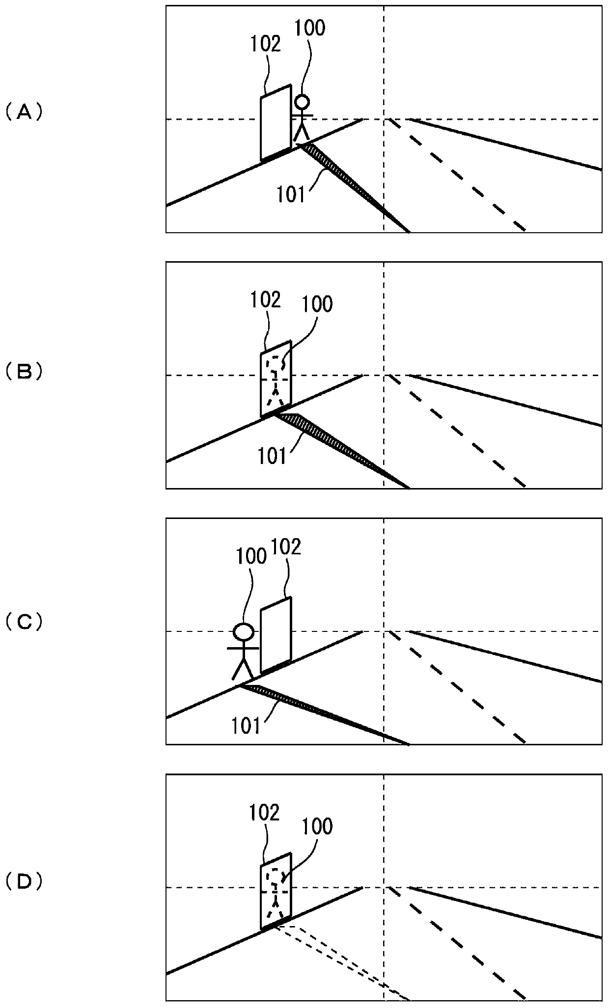
However, for example, in the case where there are many obstructions such as street trees arranged on the street, pedestrians are blocked by the obstructions, and the position of pedestrians cannot be detected.
When this period is repeated in a relatively short period, the turning on and off of the marker light becomes frequent, which makes the driver feel uncomfortable.
In addition, when there are many pedestrians, the marking light is usually controlled to be irradiated to the nearest pedestrian. However, when the position of the nearest pedestrian cannot be detected many times in a short period of time, it is frequently switched each time. Marker light for the nearest pedestrian and marker light for the next closest pedestrian
Such a state also makes the driver feel a sense of disobedience.

Method used


Image

  • Vehicle lamp control device and control method, and vehicle lamp system
  • Vehicle lamp control device and control method, and vehicle lamp system
  • Vehicle lamp control device and control method, and vehicle lamp system

Examples


Embodiment Construction

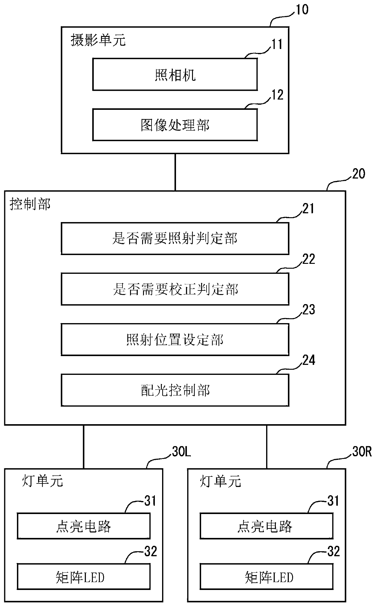
[0025] figure 1 It is a diagram showing the configuration of a vehicle lighting system according to one embodiment. The illustrated vehicular lighting system is a vehicular lighting system for notifying the driver of the own vehicle of the presence of pedestrians by irradiating light extending toward pedestrians located around the own vehicle, that is, marker light, and includes an imaging unit 10, a control unit 20 and a pair of lamp units 30L, 30R.

[0026] The imaging unit 10 is used to detect the positions of pedestrians around the host vehicle, and includes a camera 11 and an image processing unit 12 . The camera 11 photographs the surrounding space of the host vehicle. The image processing unit 12 detects the position of a pedestrian by performing predetermined image recognition processing based on the video (image) obtained by the camera 11 , and supplies the position data to the control unit 20 .

[0027] The control unit 20 controls the pair of light units 30L and ...


PUM


Abstract

The invention provides a vehicle lamp control device and control method, and a vehicle lamp system, which can alleviate the strange feeling of a driver when the driver is illuminated. The vehicle lampcontrol device is used to control a vehicle lamp, which can carry out selective irradiation. The vehicle lamp control device controls the vehicle lamp to irradiate marking light extending to the position of a first object body located on the periphery of the vehicle. When the current position of the first object is not detected, the current position of the first object is estimated on the basis of the previously detected position of the first object, and the vehicle lamp is irradiated with marker light extending to the estimated position.

Description

technical field [0001] The present invention relates to a control technology for a vehicle lamp that emits light (marker light) indicating the direction of the presence of the pedestrian in order to notify the driver of the presence of the pedestrian. Background technique [0002] There is known a lighting system for a vehicle that emits light in a direction indicating the presence of a pedestrian in order to notify the driver of the presence of the pedestrian (for example, refer to JP-A-2018-98066). In such a system, for example, a camera photographs a pedestrian, the position of the pedestrian is determined, and light is irradiated toward the position. The light used to notify the pedestrian is called a marker light. At this time, the relative positions of the pedestrian and the vehicle change according to the movement of both, but since the detection result of the position of the pedestrian is updated at predetermined intervals, the irradiation position of the marker lig...

Claims


Application Information

Patent Timeline
IPC IPC(8): B60Q1/28B60Q1/50B60R16/023
CPCB60Q1/28B60Q1/50B60R16/023Y02B20/40
Inventor 细山勇骑
Owner STANLEY ELECTRIC CO LTD
Learn More