
A smart home mosquito control device

A smart home and anti-mosquito technology, which is applied to devices for capturing or killing insects, cleaning methods and utensils, chemical instruments and methods, etc., which can solve problems such as mosquito adhesion, difficulty in cleaning, and affecting bedroom air quality

Active Publication Date: 2021-11-19
武汉市鸣晨科技有限公司
View PDF9 Cites 0 Cited by
  • Summary
  • Abstract
  • Description
  • Claims
  • Application Information

AI Technical Summary

Problems solved by technology

[0003] At present, the existing smart home mosquito control equipment attracts mosquitoes by emitting lights, and then electrocutes the mosquitoes to death through the power grid. The burning smell affects the air quality in the bedroom, and the mosquitoes stick to the grid and it is difficult to clean

Method used


Image

  • A smart home mosquito control device
  • A smart home mosquito control device
  • A smart home mosquito control device

Examples


Embodiment 1

[0026] see Figure 1-Figure 4 :

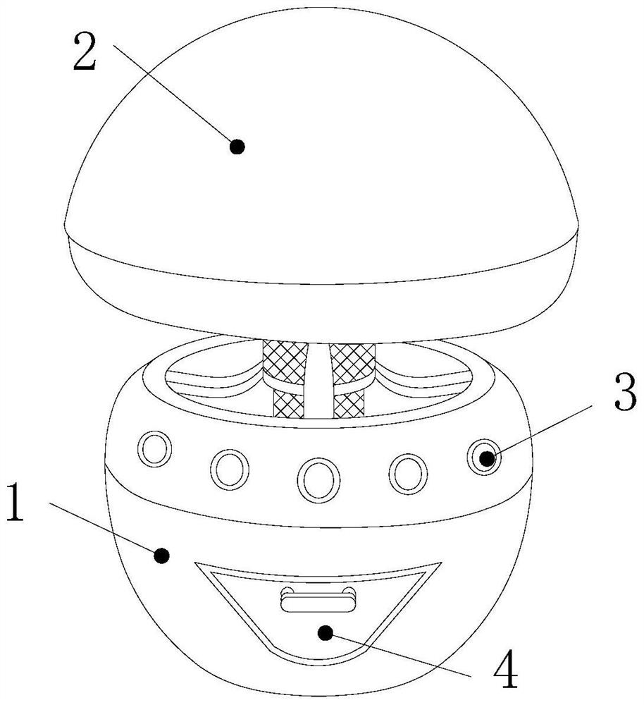
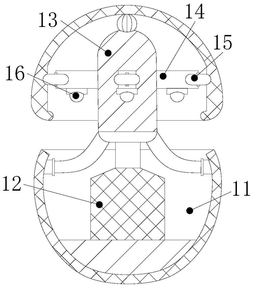
[0027] A smart household mosquito control device, the structure of which includes a mosquito control platform 1, an upper cover 2, a button 3, and a cleaning cabinet 4. The upper cover 2 is installed directly above the mosquito control platform 1, and the button 3 is embedded in the mosquito control unit. On the surface of the table 1, the cleaning cabinet 4 is connected to the front end of the mosquito killing table 1 through movable engagement. Mosquito lamp 16, the storage cavity 11 is embedded in the mosquito killing platform 1, the bottom of the support platform 12 is connected to the lower inner wall of the storage cavity 11 by welding, the electric mosquito cover 13 and the support platform 12 are located on the same axis, so The support rod 14 is connected to the outer surface of the electric mosquito cover 13 by welding, the runner 15 is connected to the end of the support rod 14 by bolts and is close to the inside of the upper cover...

Embodiment 2

[0032] see Figure 5-Figure 7 :

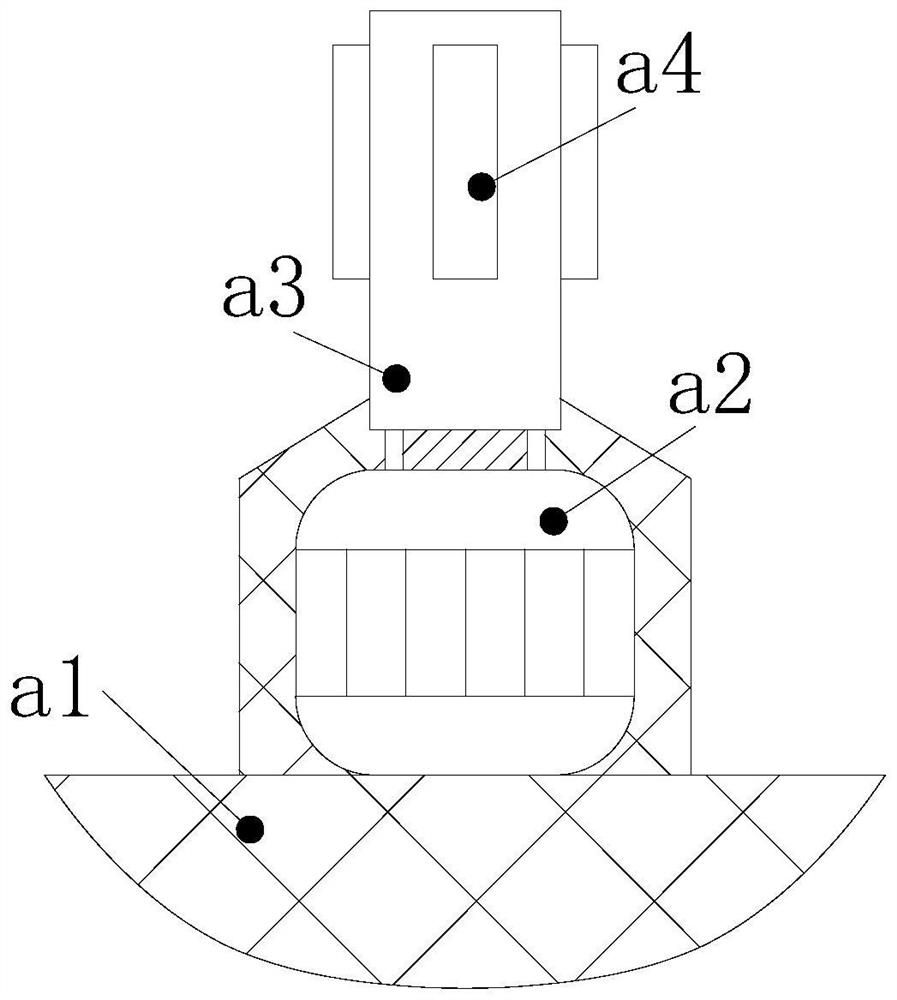
[0033] In the figure, the interior of the electric mosquito cover 13 includes a positioning rod 131, a rotating shaft 132, and a slot 133. One end of the positioning rod 131 is connected to the inner wall of the electric mosquito cover 13 by welding, and the surface of the rotating shaft 132 is connected to the other end of the positioning rod 131. Welding, the card slot 133 is embedded in the inside of the rotating shaft 132 and is located on the same axis, the positioning rods 131 have six, and are annularly distributed between the rotating shaft 132 and the electric mosquito cover 13, and the card slot 133 and the rotating rod a3 The block a4 is engaged with each other, which is beneficial for the electric mosquito cover 13 to follow the rotating shaft 132 to rotate.

[0034] In the figure, the surface of the electric mosquito cover 13 includes a grid b1, a swing rod b2, and a brush b3. The grid b1 is installed on the surface of the electr...


PUM


Abstract

The invention discloses a mosquito killing device for smart home. , the support table includes sand blocks, motors, rotating rods, and clamping blocks. The clamping blocks include suction cups and anti-skid strips. The interior of the electric mosquito cover includes a positioning rod, a rotating shaft, and a card slot. The surface of the electric mosquito cover includes a power grid, a swing rod, and a brush. The brush includes The brush head, the limit spring, the motor drives the rotating rod to rotate, and the rotating shaft and the electric mosquito cover are driven to rotate under the engagement of the clamping block and the clamping groove. Avoid electrocuted mosquitoes from accumulating near the electric mosquito cover, so as not to continuously shock the electrocuted mosquitoes, resulting in a burning smell and affecting the air quality of the bedroom.

Description

technical field [0001] The invention relates to the field of smart home, in particular to a smart home mosquito killing device. Background technique [0002] In summer, when the temperature is high, mosquitoes are infested in large numbers. Mosquitoes bite people. Smart home mosquito killing equipment is used to kill mosquitoes in bedrooms, so as to avoid mosquitoes from biting people and affecting people's sleep quality. [0003] At present, the existing smart home mosquito control equipment attracts mosquitoes by emitting lights, and then electrocutes the mosquitoes to death through the power grid. The burning smell affects the air quality in the bedroom, and the mosquitoes stick to the grid and it is difficult to clean. Contents of the invention [0004] For the existing smart home mosquito killing equipment, it attracts mosquitoes by emitting lights, and then electrocutes the mosquitoes to death through the power grid. The burnt smell affects the air quality in the b...

Claims


Application Information

Patent Timeline
Patent Type & Authority Patents(China)
IPC IPC(8): A01M1/04A01M1/22B08B1/04B08B13/00
CPCA01M1/04A01M1/223B08B13/00B08B1/12B08B1/32
Inventor 邹波
Owner 武汉市鸣晨科技有限公司
Learn More