Fertilizing machine for agricultural planting

A fertilizer applicator and agricultural technology, applied in the agricultural field, can solve the problems of affecting rice fertilization, clogging of the discharge port, sticking, etc.

Inactive Publication Date: 2020-07-24
张凌龙
View PDF0 Cites 0 Cited by
  • Summary
  • Abstract
  • Description
  • Claims
  • Application Information

AI Technical Summary

Problems solved by technology

[0003] Due to the different water levels in the paddy fields where rice is planted in the existing fertilizers for agricultural planting, when fertilizing the paddy fields with deep water levels, the water in the paddy fields will splash out at the discharge port of the fertilizer applicator, so that the fertilizer will be discharged at the same time. The mouth is damp and sticks to the discharge port, causing the discharge port to be blocked and affecting the fertilization of rice

Method used


Image

  • Fertilizing machine for agricultural planting
  • Fertilizing machine for agricultural planting
  • Fertilizing machine for agricultural planting

Examples


Embodiment 1

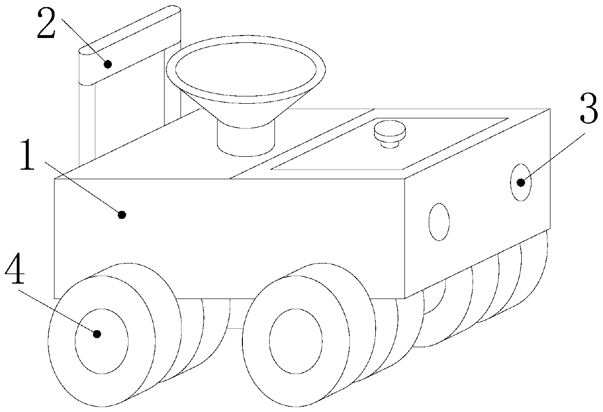
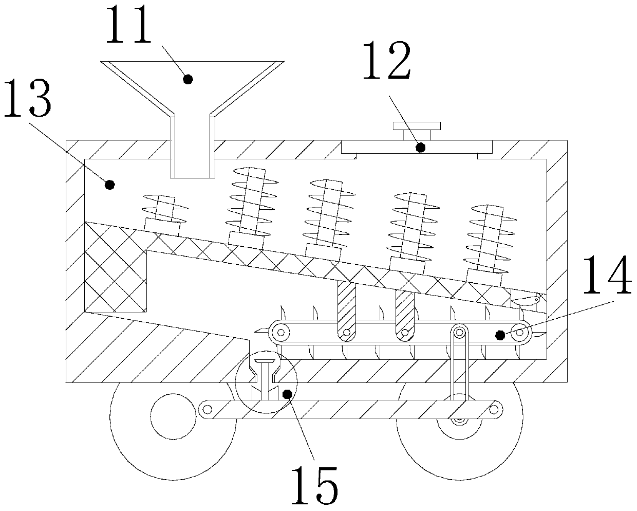
[0026] See Figure 1-Figure 4 :

[0027] A fertilizer applicator for agricultural planting, which structure includes a fertilizer transport box 1, a handle 2, a lighting lamp 3, and a movable wheel 4. The bottom of the fertilizer transport box 1 is equipped with a movable wheel 4, and the handle 2 is connected to the fertilizer transport by welding. On one side of the box 1, the lighting lamp 3 is embedded on the other side of the fertilizer transport box 1. The fertilizer transport box 1 includes a feeding hopper 11, a cleaning cover 12, a mixing chamber 13, a guide belt 14, and a fertilizer tank 15. The feeding hopper 11 and the cleaning cover 12 are respectively embedded on the upper surface of the fertilizer transport box 1, the mixing chamber 13 is embedded in the inner wall of the fertilizer transport box 1, and the guide belt 14 is connected to the inside of the fertilizer transport box 1 through a gap. The fertilization tank 15 penetrates the bottom of the fertilizer tran...

Embodiment 2

[0032] See Figure 5-Figure 7 :

[0033] In the figure, the fertilization trough 15 includes a discharge port b1, a lifting rod b2, and a limit plate b3. The discharge port b1 and the fertilization tank 15 are an integrated structure, and the lifting rod b2 is connected to the discharge port through a gap. Inside b1, the limiting plate b3 is embedded on the top of the lifting rod b2, and the limiting plate b3 is of a truncated cone shape and is arranged above the discharge port b1 to prevent the lifting rod b2 from falling out of the fertilizing tank 15.

[0034] In the figure, the lifting rod b2 includes a solid tube b21, a fertilization hole b22, a fertilization tube b23, and a guide plate b24. The solid tube b21 is embedded in the upper half of the lifting rod b2, and the fertilization hole b22 is embedded in the lifting rod. On surface b2, the fertilization pipe b23 is located below the solid pipe b21, the guide plate b24 is connected to the outside of the fertilization pipe b...


PUM


Abstract

The present invention discloses a fertilizing machine for agricultural planting. The fertilizing machine structurally comprises a fertilizer conveying box, a handle, illuminating lamps and moving wheels, wherein the fertilizer conveying box comprises a feeding hopper, a cleaning cover, a stirring cavity, a material guide belt and a fertilizing groove; the stirring cavity comprises a driving machine, rotating teeth, stirring rods, a discharging hole and a baffle; the stirring rod comprises a rotating shaft, a stirring paddle, a rotating groove and a clamping block; the fertilizing groove comprises a material outlet, a lifting rod and a limiting plate; the lifting rod comprises a solid pipe, a fertilizing hole, a fertilizing pipe and a guide plate; and the guide plate comprises a supportingspring, a fertilizing opening and a positioning rod. The handle is pushed to move the fertilizer conveying box, at the moment, the moving wheels rotate for driving the positioning rod, the fertilizingopening and the supporting spring to move, the supporting spring pulls the guide plate to move, and the lifting rod is lifted up and down in the fertilizing groove; and in the lifting process of thelifting rod, the upper surface of the guide plate is provided with a circular truncated cone-shaped groove and the diameter of the upper surface of the groove is greater than that of the lower surfaceof the groove, so that water in a paddy field is discharged downwards and the influence on paddy fertilization due to blockage of the material outlet after the water in the paddy field enters the fertilizer conveying box is avoided.

Description

Technical field [0001] The invention relates to the field of agriculture, in particular to a fertilizer applicator for agricultural planting. Background technique [0002] The agricultural fertilizer applicator is one of the devices commonly used in agriculture. The fertilizer applicator for agricultural planting can replace manual labor and automatically fertilize agricultural products. It is characterized by high speed and can prevent people from contacting fertilizers and causing harm to the human body. [0003] At present, the existing fertilizer applicator used for agricultural planting, due to the different water level in the rice field where rice is grown, when fertilizing the rice field with a deeper water level, the water in the rice field will splash on the outlet of the fertilizer applicator, causing the fertilizer to be discharged. The mouth is damp and sticks to the discharge port, causing the discharge port to block and affect the fertilization of rice. Summary of th...

Claims


Application Information

Patent Timeline
Patent Type & Authority Applications(China)
IPC IPC(8): A01C15/12A01C15/00
CPCA01C15/00A01C15/005A01C15/12
Inventor 张凌龙
Owner 张凌龙
Why Eureka
Try Eureka