Eureka AIR delivers breakthrough ideas for toughest innovation challenges, trusted by R&D personnel around the world.

Rotary electric machine

A technology of rotating electrical machines and rotors, applied in the field of rotating electrical machines, which can solve the problems that the cooling medium is not easy to scatter and cannot cool the coils, etc., and achieves the effect of good efficiency and improved rotation efficiency

Inactive Publication Date: 2020-07-21
HONDA MOTOR CO LTD
View PDF7 Cites 0 Cited by
  • Summary
  • Abstract
  • Description
  • Claims
  • Application Information

AI Technical Summary

Problems solved by technology

[0007] However, when the wall body is provided on the inner peripheral surface side of the stator than the outlet opening of the cooling medium, the cooling medium flowing out from the outlet opening is blocked by the wall body, so the cooling medium may not easily scatter to the coils of the stator, and it may not be possible to Efficient cooling of coils

Method used


Image

  • Rotary electric machine
  • Rotary electric machine
  • Rotary electric machine

Examples


no. 1 approach

[0029]

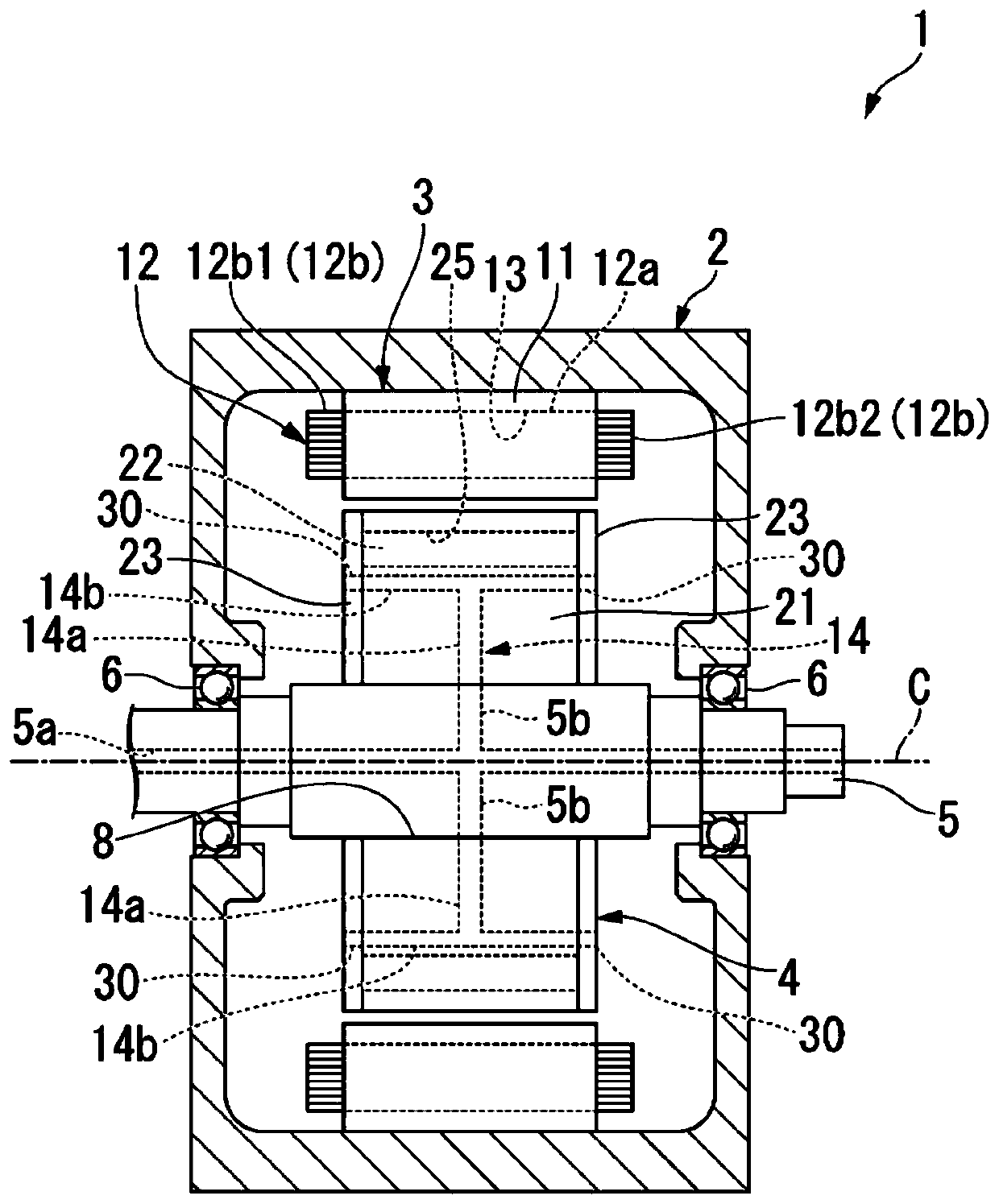
[0030] figure 1 It is a schematic configuration diagram showing the overall configuration of the rotating electrical machine 1 according to the first embodiment. figure 1 It is a figure including the cross section cut with the imaginary plane containing the axis C.

[0031] Such as figure 1 As shown, the rotating electric machine 1 includes a housing 2, a stator 3, a rotor 4, an output shaft 5, and a cooling medium supply mechanism (not shown).

[0032] The case 2 is formed in a cylindrical box shape for accommodating the stator 3 and the rotor 4 . A cooling medium (not shown) is accommodated in the casing 2 . A part of the stator 3 is arranged in a state immersed in the cooling medium in the case 2 . For example, ATF (Automatic Transmission Fluid), which is hydraulic oil used for transmission lubrication, power transmission, and the like, is used as the cooling medium.

[0033] The output shaft 5 is rotatably supported by the housing 2 . exist figure 1 In , ...


PUM


Abstract

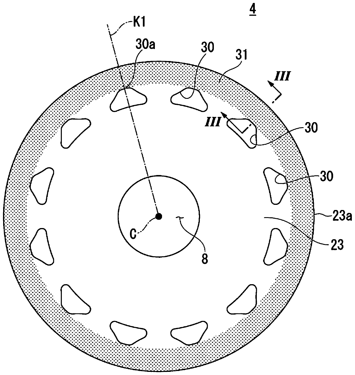
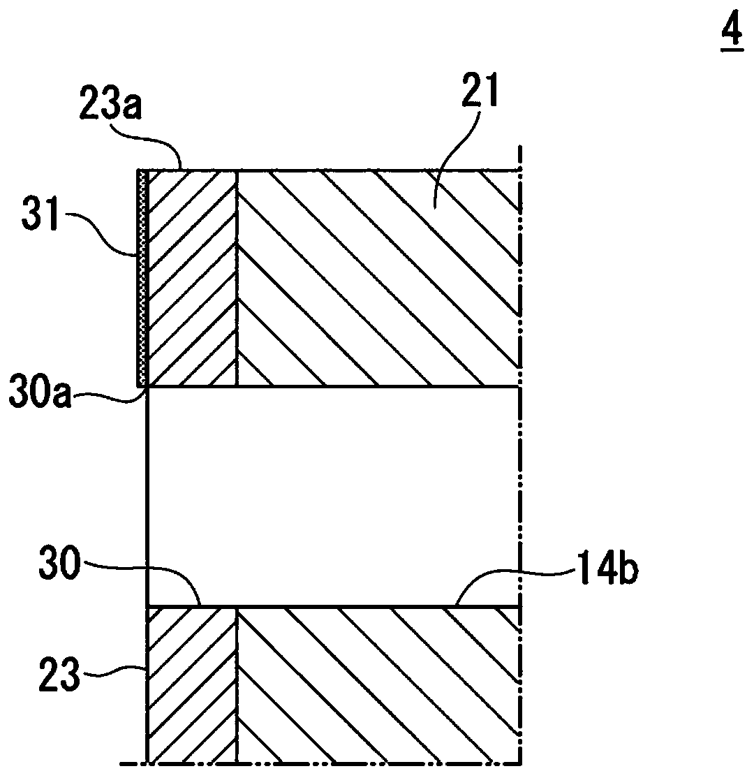
The invention provides a rotary electric machine capable of improving the rotation efficiency of the rotary electric machine and cooling a coil with good efficiency. A rotary electric machine of the embodiment includes a stator including a cylindrical stator core, and a coil mounted on the stator core, and a rotor 4 disposed radially inward of the stator, wherein the rotor includes a rotor core having a rotor internal flow path through which a refrigerant is able to flow by axial center cooling, and an end surface plate 23 disposed at an end of the rotor core in an axial direction, and the endsurface plate 23 includes a refrigerant flow hole 30 configured to communicate with the rotor internal flow path, and a surface treatment portion 31 disposed at least between the refrigerant flow hole 30 and an outer peripheral edge 23a of the end surface plate, and a surface tension of the surface treatment portion 31 is smaller than that of the end surface plate 23.

Description

[0001] This application is based on Japanese Patent Application No. 2019-003674 (filing date 2019.1.11) and enjoys priority benefits from this application. This application refers to this application, thereby including the entire content of this application. technical field [0002] This invention relates to rotating electric machines. Background technique [0003] In a rotating electric machine mounted on a hybrid vehicle, an electric vehicle, or the like, a magnetic field is formed in a stator core by supplying a current to a coil, and a magnetic attraction force and a magnetic repulsion force are generated between a rotor magnet and the stator core. Thus, the rotor rotates relative to the stator. [0004] The rotary electric machine generates heat due to operation, and thus is cooled by the cooling medium. For example, cooling medium flow paths are provided inside the rotor from the radially inner side to the radially outer side. For example, the cooling medium tempora...

Claims


Application Information

Patent Timeline
Patent Type & Authority Applications(China)
IPC IPC(8): H02K1/32H02K5/20H02K9/19
CPCH02K1/32H02K5/20H02K9/19
Inventor 山口直志岸亨仲野茂司户贺崎基山口健太郎
Owner HONDA MOTOR CO LTD
Why Eureka
Eureka Blog
Learn More