
Anti-shake system for miniature camera shooting

A micro-camera and anti-shake technology, which is applied to the focusing device of the projector, the focusing device of the camera, and optics, etc., can solve the problems of blurred images, complicated procedures, and high costs, and achieve rapid increase in production capacity and rapid and accurate production , cost reduction effect

Active Publication Date: 2020-07-21
友华科技(香港)有限公司
View PDF8 Cites 0 Cited by
  • Summary
  • Abstract
  • Description
  • Claims
  • Application Information

AI Technical Summary

Problems solved by technology

[0006] Tilt lens (Lens tilt): the image sensor is fixed to the bottom of the camera housing, and the lens is tilted; but this method can only compensate for small amplitude vibrations (the actual test can only reach a range of less than 0.5 degrees), and the lens Tilting with the image sensor will also cause blurred images at the four corners of the camera, which is its main disadvantage
[0007] Tilting the entire camera (CCM Tilt): mainly to solve the problem of image blur in the four corners above, especially the image sensor and the lens need to be integrated in the same body, and two movement angles are compensated; but this disadvantage is that the size cannot be small At the same time, the rigidity of the image cable seriously affects the pass rate and its main disadvantage
[0008] Lens Shift: The image sensor is fixed to the bottom of the camera housing, and the lens performs a translational movement; although this method is currently the only way to achieve miniaturization while taking into account the image quality, such as US7,881,598 B1 translational OIS, but the number of parts is too many, and the assembly requires complicated procedures, resulting in high cost, which is its main disadvantage

Method used


Image

  • Anti-shake system for miniature camera shooting
  • Anti-shake system for miniature camera shooting
  • Anti-shake system for miniature camera shooting

Examples


Embodiment Construction

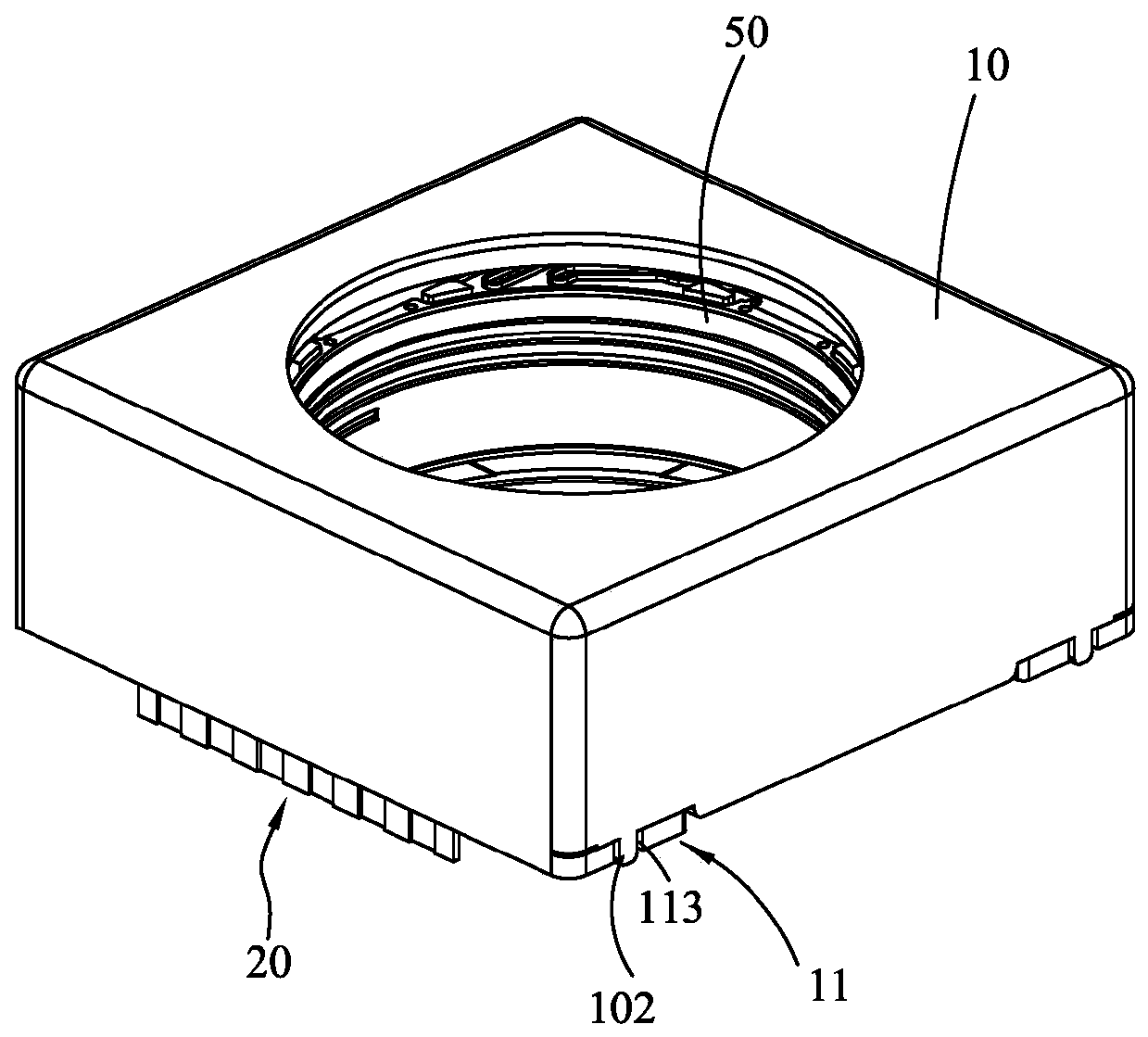
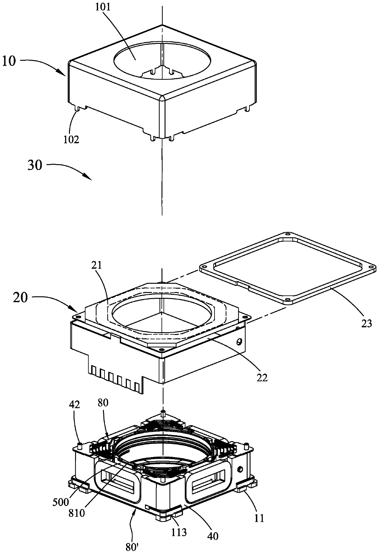
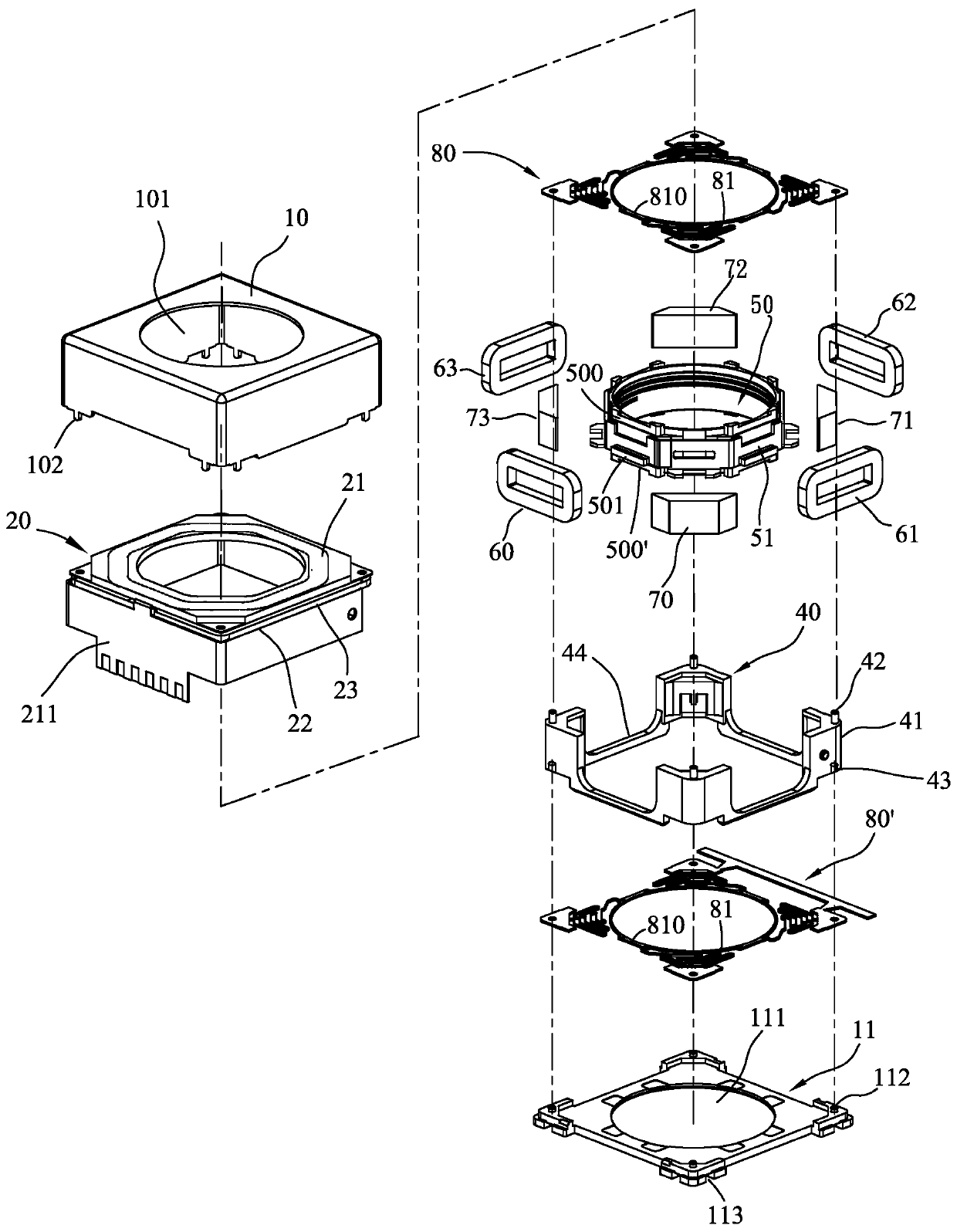
[0056] Please see figure 1 , figure 2 , image 3 As shown, the present invention at least includes:

[0057] A non-magnetic permeable upper cover 10 and a base 11 all have a middle hole 101, 111, which can be fitted with nail claws 102 and buckle grooves 113 to form the outer shell of the anti-shock system; wherein the base 11 and There are stud posts 112 combined with internal components at four corners.

[0058] A flexible circuit board 20, located in the inside of the outer shell, has a flexible board coil 21 in a horizontal direction, and a vertical circuit substrate 211 connected by the side of the flexible board coil 21, and the flexible board coil 21 and the circuit A gap 22 is formed between the substrates 211; a spacer 23 is accommodated in the gap 22 to provide a movable stroke of the mover part in the Z-axis movement direction; image 3 The shown flexible circuit board 20 is connected with a vertical circuit substrate 211 surrounded by four sides by one side o...


PUM


Abstract

The invention provides an anti-shake system for miniature camera shooting, which is mainly characterized in that a flexible circuit board is arranged at four inner peripheries and the top of the system, and comprises two pairs (four) of shake-proof coils and a focusing coil which are accommodated in the flexible circuit board; a bracket is arranged with four corner seats, and the bracket is attached to the inner edge of the flexible circuit board; the four shake-proof coils are arranged among the four corner seats of the bracket, and every two shake-proof coils are oppositely arranged in series to form the stator part of the hand shock prevention system. In addition, a magnetic yoke is arranged around a camera shooting objective lens bearing, four magnets are arranged on the periphery of the objective lens bearing respectively, and the four magnets and the four shake-proof coils are arranged at intervals to form the mover part of the hand shock prevention system; and an upper elastic sheet and a lower elastic sheet are respectively connected with the stator part and the rotor part to form the anti-hand-shake system capable of independently moving in the X-Y-Z axis.

Description

technical field [0001] The invention relates to an anti-shake system for miniature cameras, in particular to an anti-shake focusing motor device that can be used as a three-dimensional three-axis magnetic circuit system, which can be widely used in miniature photographic equipment or matched with mobile phone camera systems Equipped, it has the advantages of saving parts and assembly costs, and not occupying a volume. Background technique [0002] While photographic devices are becoming thinner and smaller, the technology of motors for micro-camera modules is becoming more and more important. Especially when mobile phones become an indispensable item in life, the need for micro-motors on mobile phones is even greater. Therefore, the requirements for the anti-shake technology of micro motors are constantly increasing. [0003] The Optical Image Stabilization (OIS) in the camera mainly uses the internal lens or photosensitive element to correct the movement of the camera such...

Claims


Application Information

Patent Timeline
Patent Type & Authority Applications(China)
IPC IPC(8): G03B5/00G03B13/34G02B27/64
CPCG03B5/00G03B13/34G02B27/646
Inventor 柯麟祥张需要张吉龙
Owner 友华科技(香港)有限公司
Learn More