
A plant trough control structure

A technology for controlling structures and plants, applied in botany equipment and methods, soilless cultivation, cultivation, etc., can solve problems such as uncontrollable growth spacing of hydroponic vegetables, and achieve the effect of improving quality

Inactive Publication Date: 2020-07-21
邱钰礎
View PDF11 Cites 0 Cited by
  • Summary
  • Abstract
  • Description
  • Claims
  • Application Information

AI Technical Summary

Problems solved by technology

Wherein, the slides straddle the tanks and can move along the tanks. The slides are provided with brackets corresponding to the tanks and provided with adsorbents. The adsorbents are sponges or materials that can absorb liquids. , so as to put the culture solution in each tank, and place vegetable seeds on the adsorption parts of each support, and form the cultivation and planting of hydroponic vegetables by absorbing the culture solution through the adsorption parts, and push the slide plate back in sequence according to the planting date, After the slide plate is pushed to the end of the tank, the growing hydroponic vegetables can be harvested, which makes the cultivation of hydroponic vegetables more convenient and more efficient; however, although the bracket of this patent moves along the tank with the slide plate, However, the volume of hydroponic vegetables will gradually increase with the growth of the plant shape, which has the disadvantage of being unable to control the growth distance required by the hydroponic vegetables in the support; therefore, how to effectively use the innovative hardware design to effectively make the Hydroponic plants of different ages can obtain their own optimal growth space, which can indeed improve the quality of hydroponic plants and effectively use the limited space to obtain a large amount of harvest. It is still the development of related industries such as hydroponic vegetable cultivation devices. Issues that the industry and related researchers need to continue to work hard to overcome and solve

Method used


Image

  • A plant trough control structure
  • A plant trough control structure
  • A plant trough control structure

Examples


Embodiment Construction

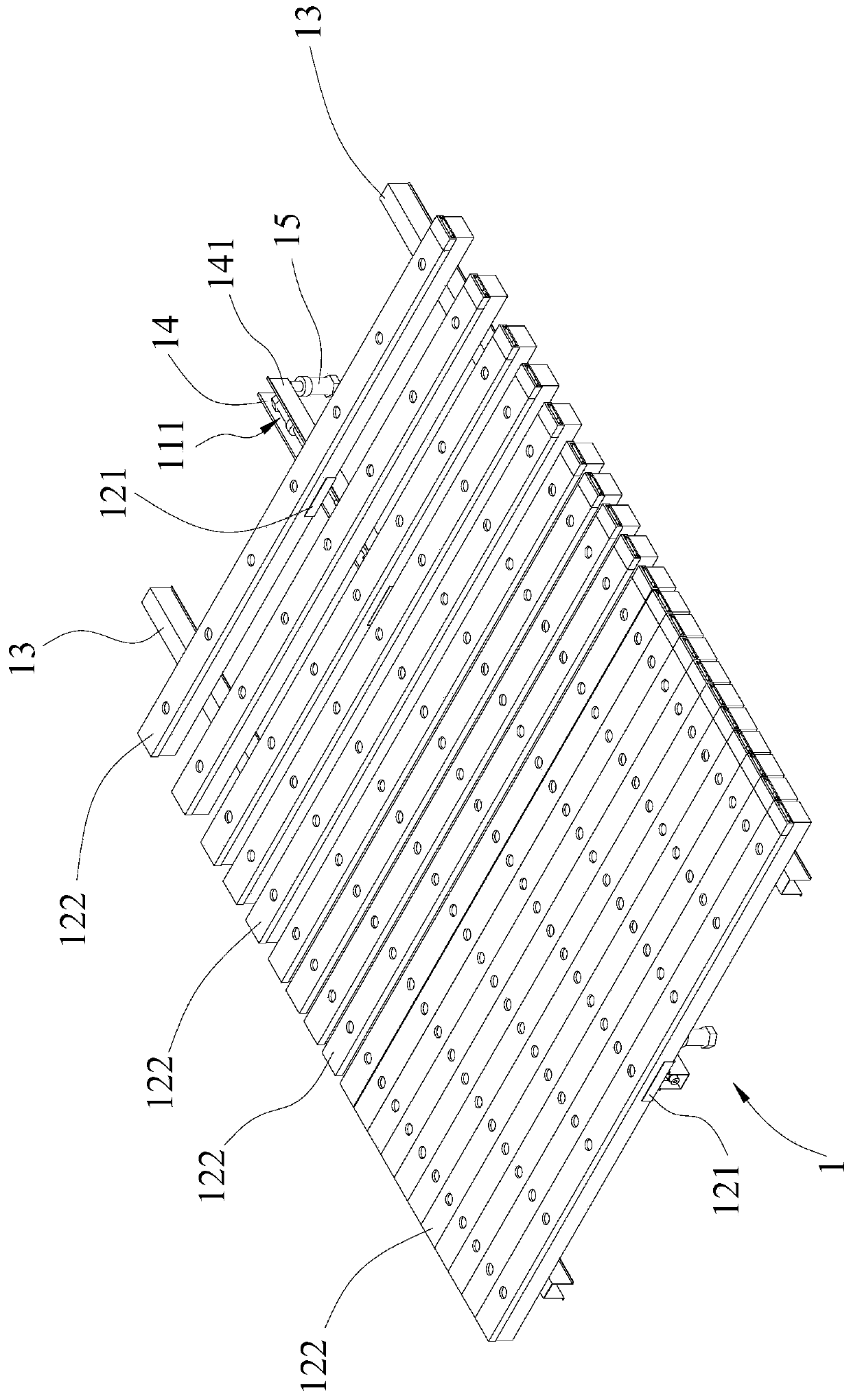
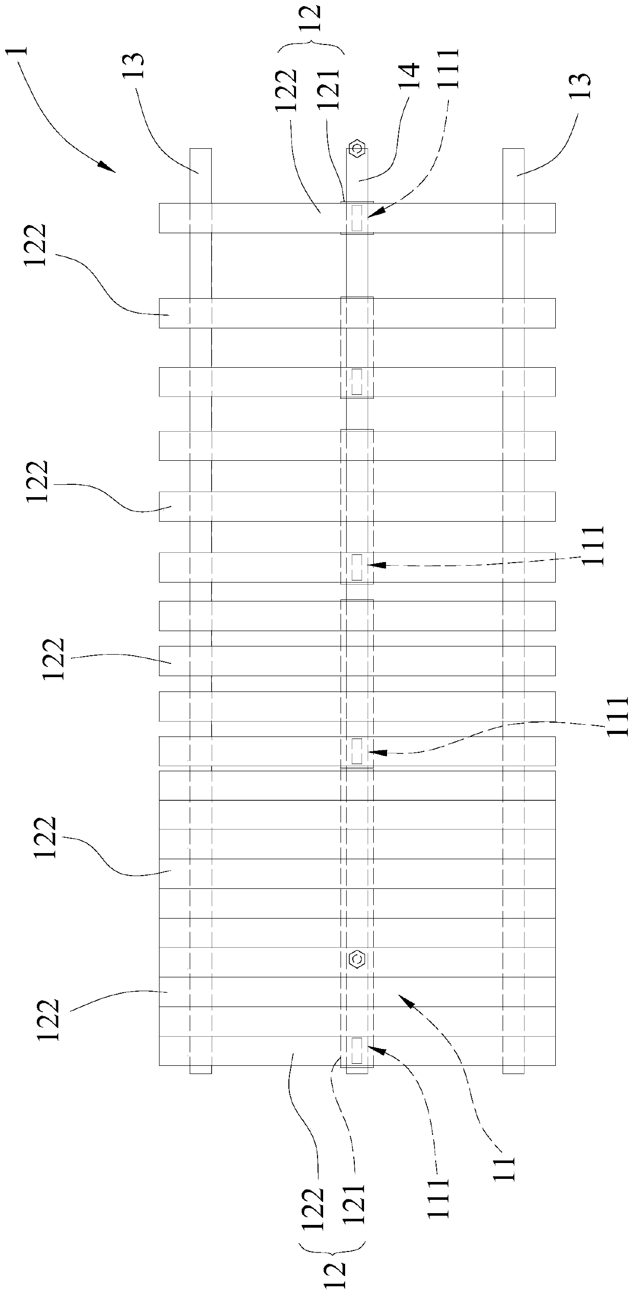
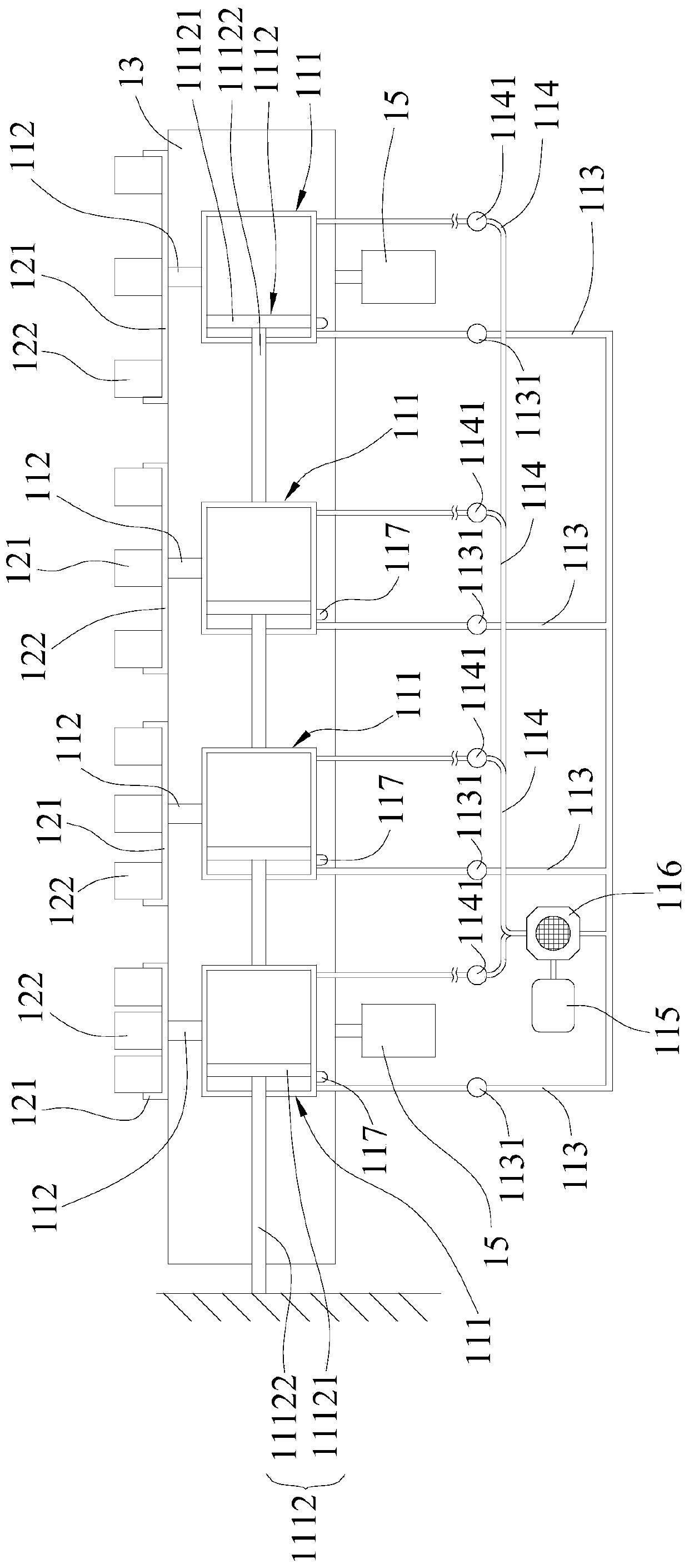
[0076] First, see Figure 1 to Figure 4 As shown, it is the three-dimensional structure diagram, the top view of the overall structure, the side view of the overall structure, and the operation schematic diagram of the lifting assembly of the first embodiment of the plant trough control structure of the present invention, wherein the plant trough control structure 1 of the present invention at least includes: a conveying mechanism 11. It includes a plurality of drive assemblies 111 and a plurality of connecting rods 112. In this embodiment, the drive assembly 111 is a fluid cylinder structure; 111 is respectively provided with a cylinder 1111, a piston rod 1112, and a first pipeline 113 and a second pipeline 114, and one end of each piston rod 1112 is movably arranged inside each cylinder 1111, and the other One end is fixed on the outside of each of the cylinders 1111, and each of the first pipelines 113 and each of the second pipelines 114 are correspondingly connected to th...


PUM


Abstract

The present invention relates to a plant trough control structure, which is a plant trough control structure that adjusts the spacing of each hydroponic plant according to the day-by-day growth of hydroponic plants so that hydroponic plants of different ages can obtain the best growth space; the present invention at least includes a conveying mechanism, a plurality of trays, a plurality of water tanks, a first support, a second support and at least one lifting component; mainly by the design of a plurality of driving components arranged horizontally, the water tank group for implanting hydroponic plant seedlings has different distances and adjusts the distance according to the daily growth of each hydroponic plant, which effectively allows hydroponic plants of different ages to obtain their own optimal growth space, which does improve the quality of hydroponic plants and can effectively use the limited space to gain advantages such as the yield of a large number of cultivation and planting.

Description

technical field [0001] The present invention relates to a plant trough control structure, in particular to a plant trough control structure that can adjust the spacing of hydroponic plants according to the daily growth of hydroponic plants so that hydroponic plants of different ages can obtain the best growth space. Background technique [0002] Generally, when hydroponic vegetables are cultivated, the seedlings are mainly placed behind the cultivation equipment, and the hydroponic vegetables are slowly grown by absorbing the nutrient solution. The conventional hydroponic vegetables need to be planted according to the growth process. Date to transplant it, for example: planted in the first area from the 1st to the 8th day, moved to the 2nd area from the 9th to the 12th day, moved to the 3rd area from the 13th to the 15th day, and so on, In order to record the date of planting, the hydroponic vegetables can be harvested when they reach the best maturity; however, this cultiva...

Claims


Application Information

Patent Timeline
IPC IPC(8): A01G31/02
CPCA01G31/02Y02P60/21
Inventor 邱钰礎
Owner 邱钰礎
Learn More