
Patch antenna with reconfigurable directional diagram

A patch antenna and pattern technology, applied in the field of wireless communication, can solve the problems of narrow bandwidth and single radiation characteristics, and achieve the effect of light weight, easy operation and improved coverage effect

Active Publication Date: 2020-07-17
深圳市芯联创展电子技术有限公司
View PDF4 Cites 7 Cited by
  • Summary
  • Abstract
  • Description
  • Claims
  • Application Information

AI Technical Summary

Problems solved by technology

Overcome the shortcomings of the existing traditional patch antennas with narrow bandwidth and single radiation characteristics

Method used


Image

  • Patch antenna with reconfigurable directional diagram
  • Patch antenna with reconfigurable directional diagram
  • Patch antenna with reconfigurable directional diagram

Examples


Embodiment

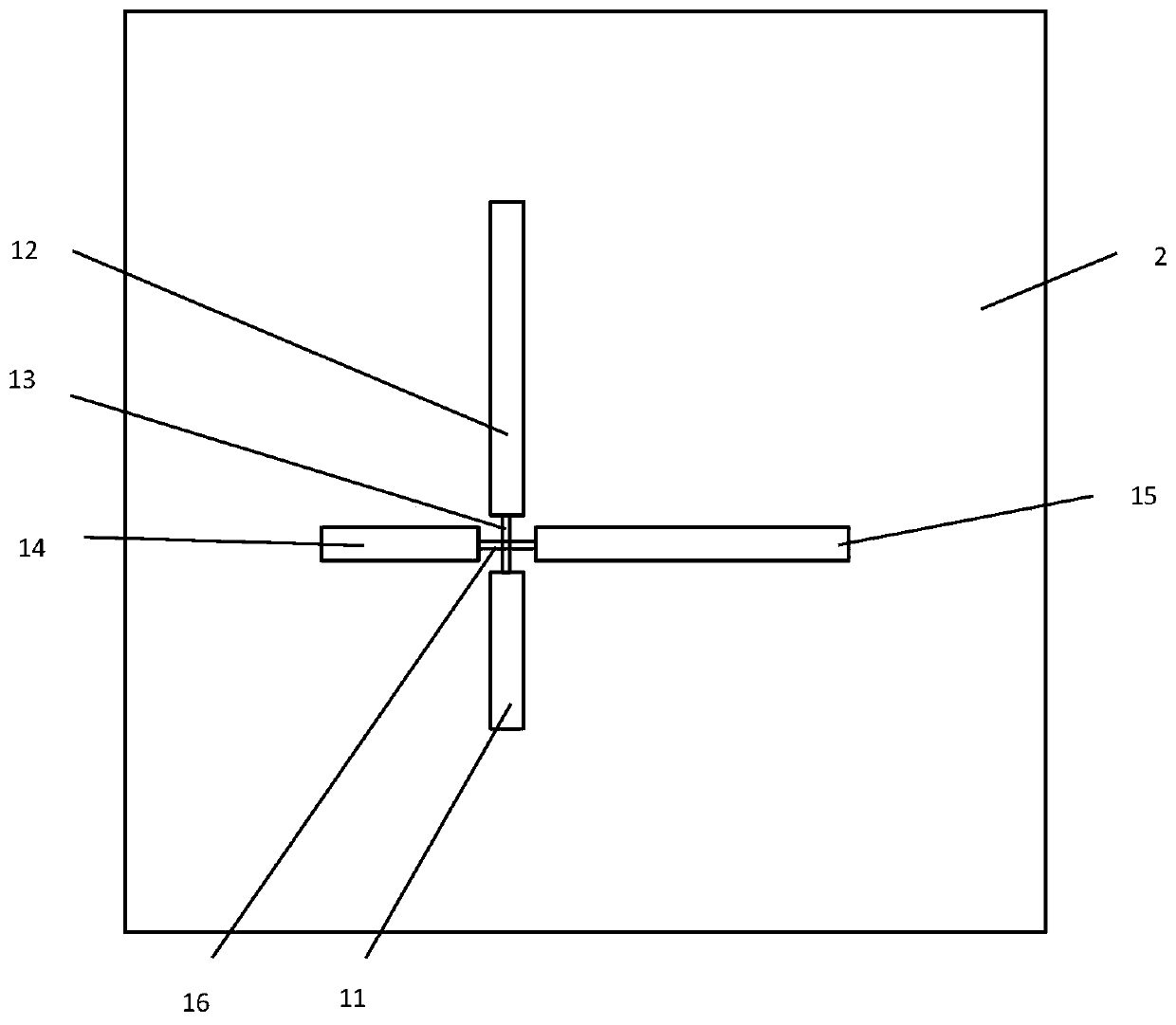
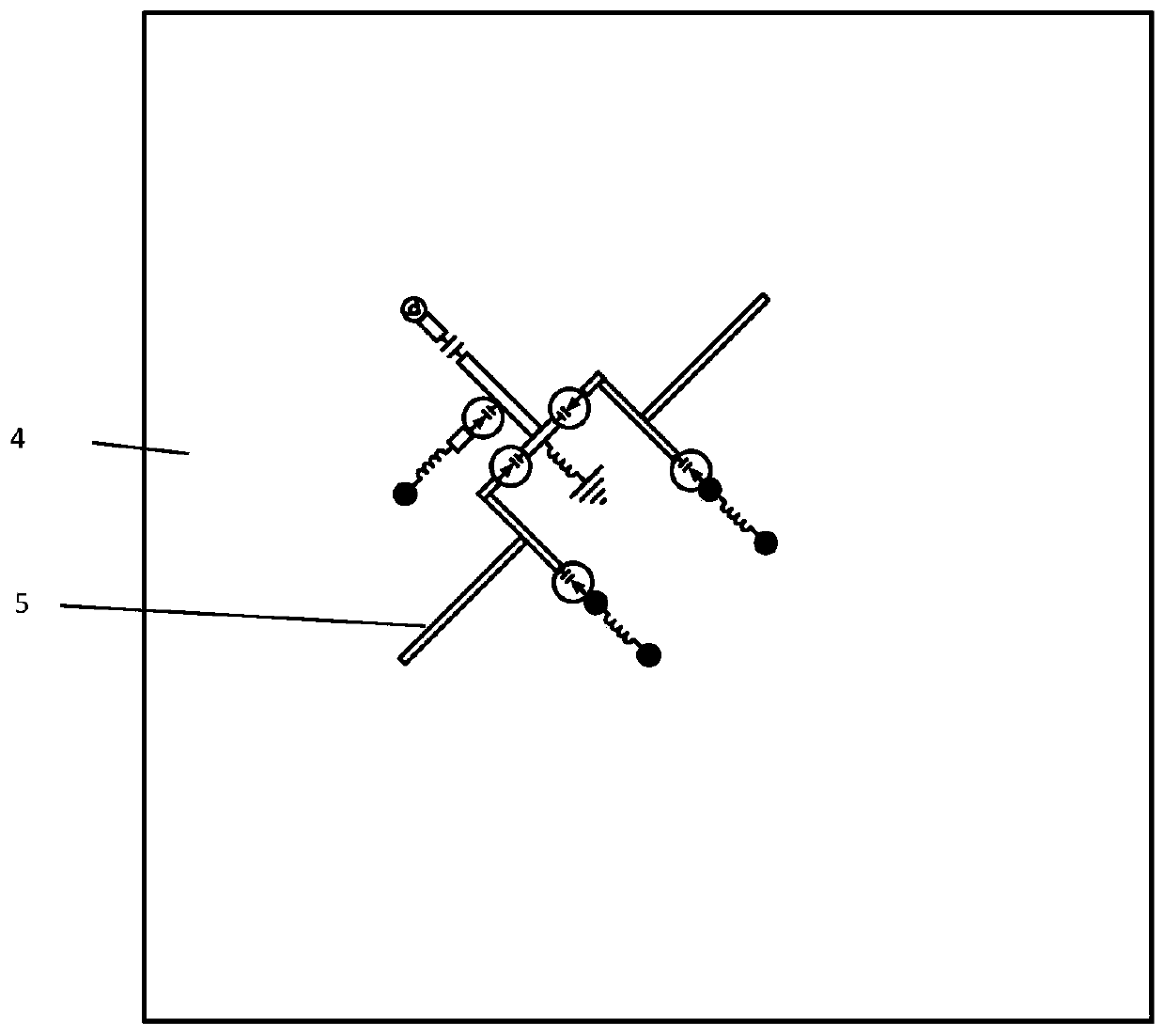
[0029] see figure 1 as well as figure 2 , a patch antenna with a reconfigurable pattern, including a microstrip resonator group 1, a first dielectric plate 2, a metal floor 3, a second dielectric plate 4, and a switchable feed network stacked sequentially from top to bottom 5; also includes working in high-order mode TM 02 Die and TM 20 mode radiation patch 7, the radiation patch 7 is suspended above the microstrip resonator group 1; the microstrip resonator group 1 is composed of a first microstrip resonator and a second microstrip resonator The strip resonator is formed; the first microstrip resonator is composed of a first microstrip line 11 and a second microstrip line 12 located in the same linear direction, and the first microstrip line 11 and the second microstrip line The lines 12 are connected by a connection line 13; the second microstrip resonator is composed of the third microstrip line 14 and the fourth microstrip line 15 located in the same straight line dire...


PUM


Abstract

The invention provides a patch antenna with a reconfigurable directional diagram. The patch antenna comprises a microstrip resonator group, a first dielectric plate, a metal floor, a second dielectricplate and a switchable feed network which are sequentially stacked from top to bottom; and the antenna also comprises a radiation patch which works in a high-order mode TM02 and a TM20, wherein the radiation patch is placed above a microstrip resonator group in a suspended manner. The microstrip resonator group is composed of a first microstrip resonator and a second microstrip resonator which are orthogonal to each other; and the feed network is used for feeding the first microstrip resonator and / or the second microstrip resonator. The antenna has the advantages of low profile, light weight,enough bandwidth, simple structure, simplicity in operation, beam reconfiguration, stable radiation and the like; a communication system can realize reconstruction of three beams by controlling a feed conduction path of the feed network under the condition of not changing a hardware structure and a station layout; and the requirements of different application scenes can be met.

Description

technical field [0001] The invention relates to the technical field of wireless communication, in particular to a patch antenna with a reconfigurable pattern. Background technique [0002] The antenna is the eyes and ears of the wireless communication system, and its performance determines the coverage effect of the system. In recent years, my country's mobile communication industry has developed vigorously, and 5G communication is gradually being commercialized. However, the frequency band of 5G communication is relatively high, the path loss is relatively large, and the coverage of macro base stations is very limited, which is prone to signal blind spots. The first challenge is undoubtedly the problem of signal coverage. In order to solve this problem, indoor distribution systems will be widely used, and micro base stations (pico base stations) will be arranged indoors and in areas with large data volumes. Due to the particularity of the application scenarios and the lar...

Claims


Application Information

Patent Timeline
Patent Type & Authority Applications(China)
IPC IPC(8): H01Q3/26
CPCH01Q3/26
Inventor 谭挺艳张晓袁涛
Owner 深圳市芯联创展电子技术有限公司
Learn More