
A composite support structure, construction system and method

A supporting structure and composite technology, which is applied in earth-moving drilling, shaft equipment, wellbore lining, etc., can solve the problems of insufficient bearing capacity of supporting structure, affecting coal mining efficiency, slow roadway forming, etc., shortening construction time, The effect of enhancing support strength and reducing labor intensity

Active Publication Date: 2021-07-30
SHANDONG JIANZHU UNIV +1
View PDF23 Cites 0 Cited by
  • Summary
  • Abstract
  • Description
  • Claims
  • Application Information

AI Technical Summary

Problems solved by technology

[0003] At present, coal is still the largest energy supply method, and more than 80% of it is underground mining, and the mining depth is increasing at a rate of 8-12m / a per year, and a large number of kilometers deep wells have appeared. As the pressure increases, the roadway pressure continues to increase. The inventors found that the traditional support structure has insufficient bearing capacity and is not suitable for deep high-stress complex roadways, and the roadways often need to be repaired
At the same time, the separation of excavation and support in the traditional support form leads to the slow formation of the roadway and affects the coal mining efficiency

Method used


Image

  • A composite support structure, construction system and method
  • A composite support structure, construction system and method
  • A composite support structure, construction system and method

Examples


Embodiment 2

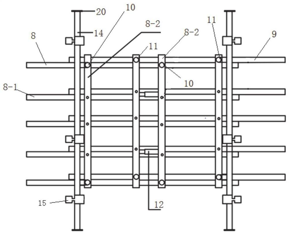
[0043] This embodiment discloses a construction system of the composite support structure described in Embodiment 1, such as image 3 As shown, it includes roadheader, bolt construction device, arc plate construction device and steel pipe construction device.

[0044]When constructing the support structure with the reinforced concrete ring inside the arc-plate ring, the roadheader, anchor rod construction device, arc-plate construction device and steel pipe construction device are set in sequence in the roadway for simultaneous construction. The roadheader is used to excavate the roadway. The bolt construction device is used to construct the bolt, the arc plate construction device constructs the arc plate ring on the tunnel part where the anchor rod has been constructed, and the steel pipe construction device is used to construct the steel pipe concrete ring on the inner side of the constructed arc plate ring.

[0045] When the construction reinforced concrete ring is located ...

Embodiment 3

[0088] Such as Figure 13 As shown, this embodiment discloses a working method of the construction system described in Embodiment 2: taking the supporting structure where the steel pipe concrete ring is located inside the arc plate ring as an example, it includes the simultaneous anchor construction process, arc Plate construction process and steel pipe construction process.

[0089] The construction method of the bolt construction procedure is as follows: the roadheader 7 excavates the roadway to excavate the roadway space, the bolt construction device moves synchronously with the roadheader under the drive of the first traveling mechanism, and after the roadheader excavates the roadway, Stop working, the first hydraulic cylinder and the second hydraulic cylinder drive the first support part and the second support part to break away from the roadway top surface, and the construction personnel erect the anchor net 47 on the inner wall of the roadway, and the construction metho...


PUM


Abstract

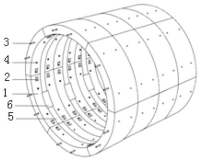
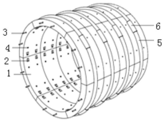
The invention relates to a compound support structure, construction system and method, comprising a plurality of arc plate rings arranged longitudinally along the roadway, the inner or outer sides of the arc plate rings are provided with steel tube concrete rings, and the arc plate rings are composed of A plurality of arc plates are spliced ​​together, and the steel pipe concrete ring is formed by splicing multiple steel pipes in sections. The arc plate ring and the steel pipe concrete ring can jointly support the roadway wall. The supporting structure of the present invention has a high bearing capacity and a construction system with high construction efficiency. Low labor intensity.

Description

technical field [0001] The invention relates to the technical field of underground engineering support, in particular to a composite support structure, construction system and method. Background technique [0002] The statements herein merely provide background information related to the present invention and do not necessarily constitute prior art. [0003] At present, coal is still the largest energy supply method, and more than 80% of it is underground mining, and the mining depth is increasing at a rate of 8-12m / a per year, and a large number of kilometers deep wells have appeared. As the pressure increases, the roadway pressure continues to increase. The inventors found that the traditional support structure has insufficient bearing capacity and is not suitable for deep high-stress complex roadways, and the roadways often need to be repaired. At the same time, the separation of excavation and support processes in the traditional support form leads to slow formation of ...

Claims


Application Information

Patent Timeline
Patent Type & Authority Patents(China)
IPC IPC(8): E21D11/00E21D11/08E21D11/10E21D11/14E21D11/18E21D11/40E21D20/00
CPCE21D11/00E21D11/083E21D11/105E21D11/14E21D11/18E21D11/40E21D20/003E21D11/12E21D23/00
Inventor 王军张兆民刘颜磊丁厚刚
Owner SHANDONG JIANZHU UNIV
Learn More