
Systems and methods for capturing carbon dioxide from group of assets that produce carbon dioxide

A carbon dioxide and asset technology, applied in chemical instruments and methods, separation methods, products, etc., to achieve emission management and economic performance optimization, reduce initial capital expenditure, and increase effective capture rate

Active Publication Date: 2020-07-17
CHNA ENERGY INVESTMENT CORP LTD +1
View PDF7 Cites 0 Cited by
  • Summary
  • Abstract
  • Description
  • Claims
  • Application Information

AI Technical Summary

Problems solved by technology

The system and method overcomes existing approaches that only seek to optimize the performance of individual sites, rather than synthesizing entire asset groups

Method used


Image

  • Systems and methods for capturing carbon dioxide from group of assets that produce carbon dioxide
  • Systems and methods for capturing carbon dioxide from group of assets that produce carbon dioxide
  • Systems and methods for capturing carbon dioxide from group of assets that produce carbon dioxide

Examples


Embodiment 1

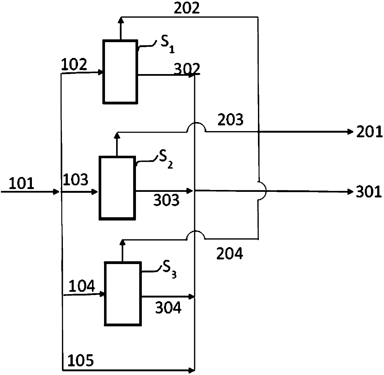
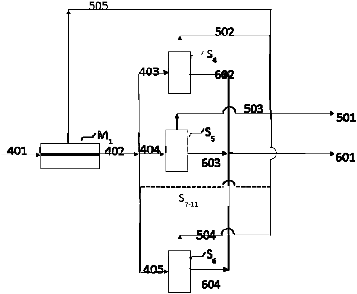
[0065] The system provided by the present invention has flexibility relative to the prior art. For example, a lower capture rate can be achieved by deploying a smaller number of small solvent modules (modular carbon dioxide capture units based on solvent capture technology), and higher capture rates can be obtained by adding modules at a later stage. This approach reduces initial capital outlay and financing requirements. Specifically, such as figure 1 As shown, a low capture rate of 30% can be achieved on the asset by deploying 3 identical modules (based on solvent capture technology, each module can capture 10% of the total flow 100%), with a mass balance shown in Table 1. Such as figure 2 As shown, by sending 100% of the exhaust stream to one membrane module (modular CO2 capture unit based on membrane Capture Technology's modular CO2 capture unit) captures enough CO2 to achieve a total capture efficiency of 90% for the asset (mass balance shown in Table 2).

[0066] Fo...

Embodiment 2

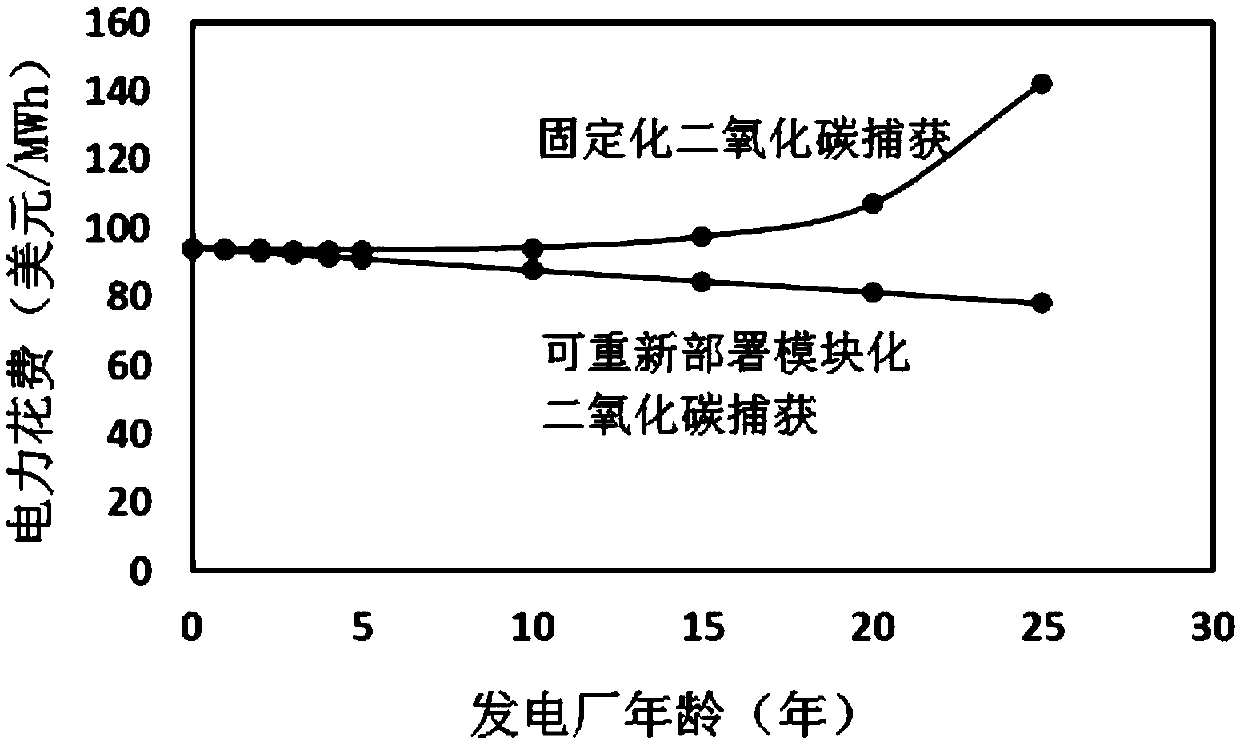
[0073] The invention also has the ability to redeploy modular CO2 capture units, the fixed costs increase with the age of the retrofit power plant because the capital expenditure of the CO2 capture unit must be funded for the remaining life of the power plant, see Singh et al ."China baseline coal-fired power plant with post-combustion CO 2 capture: 2.Techno-economics."International Journal of Greenhouse Gas Control 78(2018):429-436. The influence of the age of power plants such as image 3 As shown (among them, CF is 57%, and CF represents the capacity factor, that is, the electricity generated by the power plant in a year divided by the electricity that the power plant can produce in a year).

[0074] As a particular asset approaches the end of its life, a modular CO2 capture unit deployed at that asset can be redeployed to another asset. This decouples the financing of the modular CO2 capture unit from the remaining useful life of the asset. The net benefit is lower costs...


PUM


Abstract

The present invention relates to the field of carbon dioxide capture, and discloses a system and a method for capturing carbon dioxide from a group of assets producing carbon dioxide, the system comprising: a group of assets comprising at least two individual assets capable of producing a carbon dioxide-containing gas stream; modular carbon dioxide capture units that are used for capturing carbondioxide in the carbon dioxide-containing gas flow generated by the asset group, wherein at least one individual asset is deployed with at least two modular carbon dioxide capture units, and at least one modular carbon dioxide capture unit operates at more than one individual asset during its service life. The system and the method provided by the invention overcome the defect that the existing method only seeks to optimize the performance of a single site instead of synthesizing the whole asset group, and the system and the method provided by the invention have flexibility and can effectivelyreduce the cost.

Description

technical field [0001] The present invention relates to the field of carbon dioxide capture, and in particular to systems and methods for capturing carbon dioxide from a carbon dioxide generating asset group. Background technique [0002] Climate change caused by greenhouse gas emissions is the driving force behind the decarbonization of electricity generation and industrial processes. Therefore, there is a need to have the ability to capture CO from exhaust gases 2 Ability. This general approach can be applied to thermal power plants fueled by coal, natural gas, or biomass and to generate 2 Gas industrial system. There are many optimized CO 2 Capture units such as CO for coal-fired power plants, natural gas power plants and industrial sources 2 capture unit. The prior art also describes modular CO 2 A capture system comprising a module deployable as a plurality of discrete units configured according to a site. [0003] Asset management related to infrastructure is m...

Claims


Application Information

Patent Timeline
Patent Type & Authority Applications(China)
IPC IPC(8): C01B32/50B01D53/00B01D53/14B01D53/22B01D53/02
CPCC01B32/50B01D53/00B01D53/1475B01D53/228B01D53/02Y02P20/151B01D53/229B01D53/18B01D2257/504B01D2258/0283B01D2259/455Y02C20/40B01D53/14B01D53/22B01D53/78B01D2258/02
Inventor 顾佑宗S·辛格郝平娇J·艾伦
Owner CHNA ENERGY INVESTMENT CORP LTD
Learn More