
Radar system operating method and radar system having improved range resolution by mutually delayed orthogonal codes

A radar system, orthogonal code technology, applied in radio wave measurement system, radio wave reflection/re-radiation, utilization of re-radiation and other directions, can solve problems such as distance resolution limitation of automotive radar system

Pending Publication Date: 2020-07-14
IEE INT ELECTRONICS & ENG SA
View PDF7 Cites 0 Cited by
  • Summary
  • Abstract
  • Description
  • Claims
  • Application Information

AI Technical Summary

Problems solved by technology

In this application, the range resolution of an automotive radar system may be limited by the sampling rate of the ADC used

Method used


Image

  • Radar system operating method and radar system having improved range resolution by mutually delayed orthogonal codes
  • Radar system operating method and radar system having improved range resolution by mutually delayed orthogonal codes
  • Radar system operating method and radar system having improved range resolution by mutually delayed orthogonal codes

Examples


Embodiment Construction

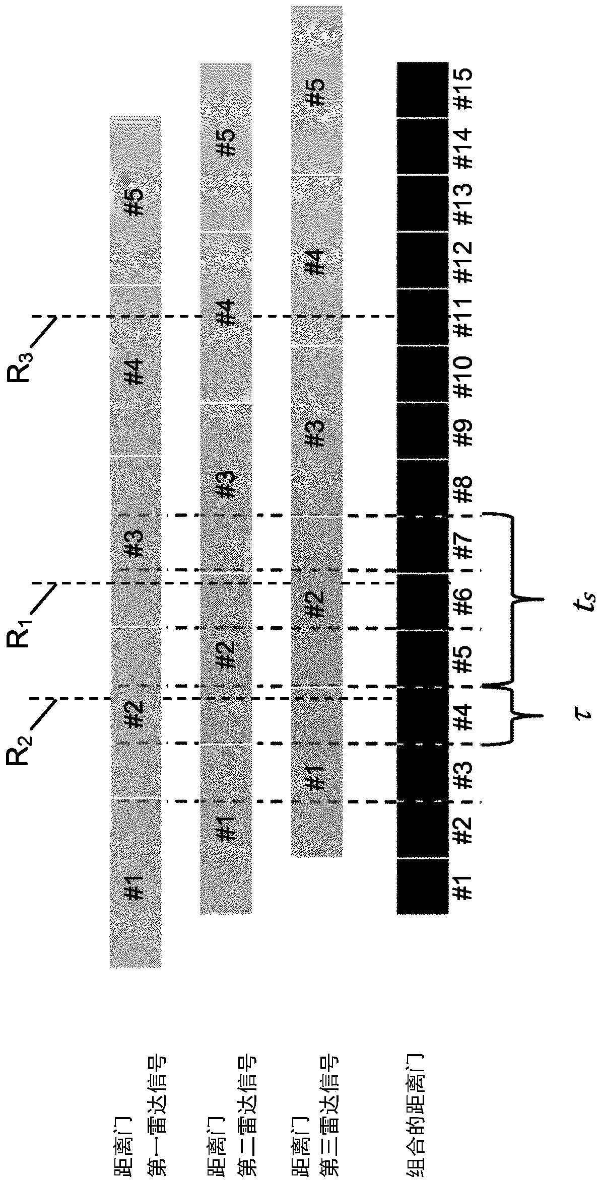
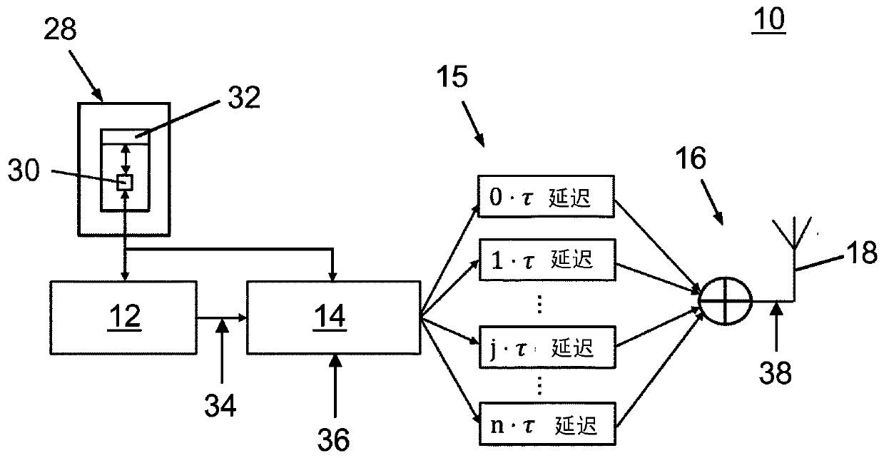
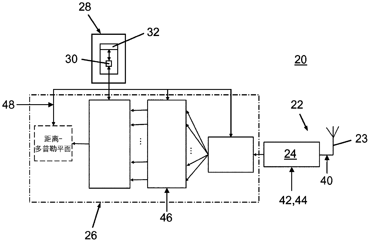
[0057] In the following, a possible embodiment of the method according to the invention for operating a modulated continuous wave radar system comprises: a transmitting side 10 , a receiving side 20 and an evaluation and control unit 28 . refer to figure 2 and image 3 A modulated continuous wave radar system is described, figure 2 and image 3 The functional schemes of the transmitting side 10 and the receiving side 12 are shown respectively. refer to Figure 5 The flowchart shown in describes the method according to the invention.

[0058] In this particular embodiment, the modulated continuous wave radar system is designed as a phase modulated continuous wave (PMCW) radar system for automotive applications, more specifically for vehicle parking assistance systems. The PMCW radar system is configured to operate at a radar carrier frequency of approximately 77 GHz.

[0059] In alternative embodiments, a modulated continuous wave radar system may also be designed as a ...


PUM


Abstract

A method of operating a modulated continuous-wave radar system at least comprises steps of transmitting (38), with a modulation frequency, a plurality of n modulated continuous radar waves that represent mutually orthogonal codes towards a scene with a potential object to be detected, wherein the transmitted modulated continuous radar waves of the plurality of modulated continuous radar waves areconsecutively transmitted with a constant time lag (tau) given by one nth of a period of the modulation frequency; digitally converting (44) a plurality of reflected and received radar signals with asampling rate (l / ts) that is equal to the modulation frequency; decoding (46) individual range information for each received radar signal; and determining (48) a range between the radar system and theobject on the basis of the decoded individual range information.

Description

technical field [0001] The present invention relates to a method of operating a modulated continuous wave radar system and an automotive continuous wave radar system operated by such a method. Background technique [0002] In the field of automotive technology, it is known to employ radar technology, in particular continuous wave (CW) radar systems, in interior and exterior automotive applications for providing improved safety in several ways. Most commonly, automotive radar systems operate in the range of about 24 GHz or about 77 GHz on the radar carrier frequency. Many automotive radar system applications (for example, parking assistance systems or seat occupant detection systems that exploit the breathing motion of passengers) require high range resolution to provide precise information about objects that may be present in the near field of the radar system. In such applications, the range resolution of an automotive radar system may be limited by the sampling rate of th...

Claims


Application Information

Patent Timeline
IPC IPC(8): G01S7/35G01S13/18G01S13/58G01S13/931
CPCG01S7/354G01S13/18G01S13/584G01S13/931G01S7/023G01S7/0233G01S7/0234G01S13/325
Inventor H-P·拜泽
Owner IEE INT ELECTRONICS & ENG SA
Learn More