Printed antenna production process

A production process and technology for printing antennas, applied in the field of wireless communication, can solve the problems of unstable antenna performance, high product scrap rate, and large equipment investment, saving man-hours and equipment occupancy, reducing process difficulty, and small equipment investment. Effect

Inactive Publication Date: 2020-07-14
中亚众诚(天津)科技有限公司
View PDF9 Cites 0 Cited by
  • Summary
  • Abstract
  • Description
  • Claims
  • Application Information

AI Technical Summary

Problems solved by technology

[0003] In order to achieve the design thickness, printing antennas must be printed multiple times in the existing technology, and each printing will produce dimensional deviation, resulting in unstable antenna performance and high product scrap rate
Because the same process is repeatedly operated, the production capacity is seriously occupied, resulting in large investment in equipment, many manual operations, low production efficiency, long production time and many other problems.

Method used


Image

  • Printed antenna production process
  • Printed antenna production process

Examples


Embodiment Construction

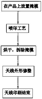
[0014] see Figure 1-Figure 2 As shown, the technical solution adopted in this specific embodiment is: a production process of a printed antenna includes the following steps: Step 1, according to the designed antenna pattern and the structure of the product, a mask is made to cover the non-printing area to prevent the printing In the process, other areas are contaminated; step 2, the positioning pattern for machine vision positioning is pre-designed on the mask, and accurate positioning can be achieved during the printing process; step 3, the mask coverage area adjusts the printing area according to actual needs The graphics and size are slightly adjusted to meet the requirements of the follow-up process; step 4, use a special printing device to execute the spraying operation of the pre-prepared special printing paste according to the pre-set printing action in the program. Printing operation; Step 5, after the jet printing operation, perform mask removal and drying operations...


PUM


Abstract

The invention discloses a printed antenna production process, and relates to the field of antenna communication. The production process comprises the following steps: 1, manufacturing a mask for covering a non-jet printing area according to a designed antenna pattern and a product structure; 2, pre-designing a positioning pattern for machine vision positioning on the mask; 3, slightly adjusting the pattern and the size of the jet printing area according to the actual demand in the mask coverage area; 4, adopting a special jet printing device, and executing a jet printing operation on the pre-blended special printing paste according to the jet printing action set in a program in advance; 5, after the jet printing operation, executing mask removal and drying operation; 6, for the dried graph, employing a laser engraving machine or mechanical equipment for completing fine trimming and shaping work. After the technical scheme is adopted, the method has the beneficial effects that the costis low, the implementation is simple, the equipment investment is small, and the quality and the yield of products can be greatly improved.

Description

technical field [0001] The invention relates to the field of wireless communication, in particular to a production process of a printed antenna. Background technique [0002] Printed antennas, simply put, are antennas that can be printed. The printed antenna is arranged on the substrate, and includes a signal feeding part and a radiator. The signal feed-in part is used for feeding in electromagnetic wave signals. The radiating body is used for sending and receiving electromagnetic wave signals, and includes a first radiating part, a second radiating part and a guiding section. The first radiating part is electrically connected to the signal feeding part, and includes an arc-shaped radiating section. The second radiating part is electrically connected to the signal feeding part and the first radiating part. The guiding section is arc-shaped, and is located on two sides of the first radiating section respectively with the second radiating section, and a first gap is formed...

Claims


Application Information

Patent Timeline
IPC IPC(8): H01Q1/38C23C26/00
CPCH01Q1/38C23C26/00
Inventor 高俊琪赵连瑞陆晓萌石路源
Owner 中亚众诚(天津)科技有限公司
Why Eureka
Try Eureka