
Automatic calcium carbide stoking robot

A robot and calcium carbide technology, which is applied in the field of calcium carbide furnace slamming, can solve the problems of low degree of freedom, small operating range, and poor maneuverability of drill rods, and achieve the effects of improving production efficiency, reducing safety hazards, and improving operating efficiency

Active Publication Date: 2020-07-14
HARBIN BOSHI AUTOMATION
View PDF7 Cites 2 Cited by
  • Summary
  • Abstract
  • Description
  • Claims
  • Application Information

AI Technical Summary

Problems solved by technology

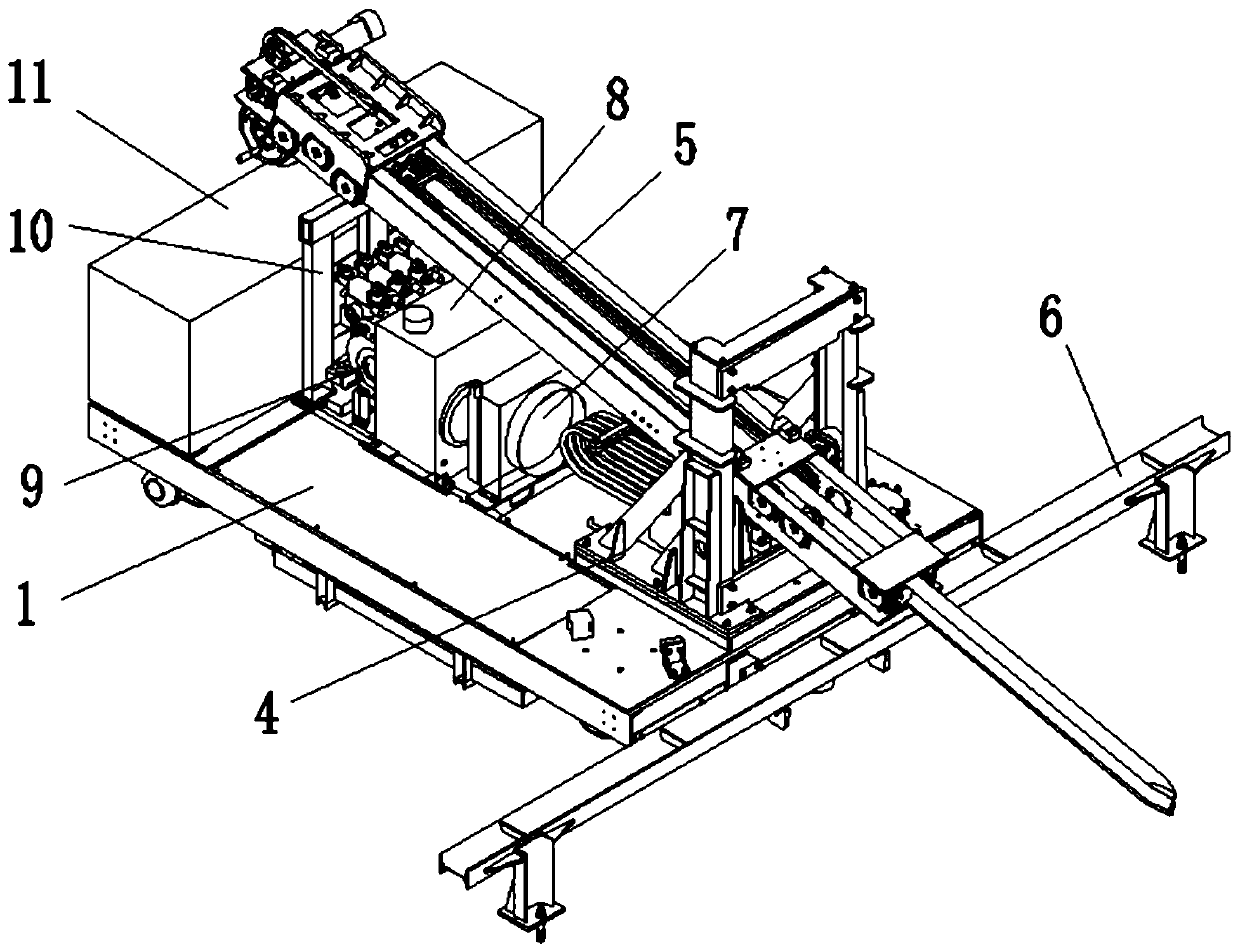
[0003] The purpose of the present invention is to provide an automatic calcium carbide furnace robot to solve the problems of poor maneuverability, small working range and low degree of freedom of chisel rods in traditional furnace furnace robots

Method used


Image

  • Automatic calcium carbide stoking robot
  • Automatic calcium carbide stoking robot
  • Automatic calcium carbide stoking robot

Examples


Embodiment Construction

[0037] Preferred embodiments of the present invention will be described in detail below with reference to the accompanying drawings.

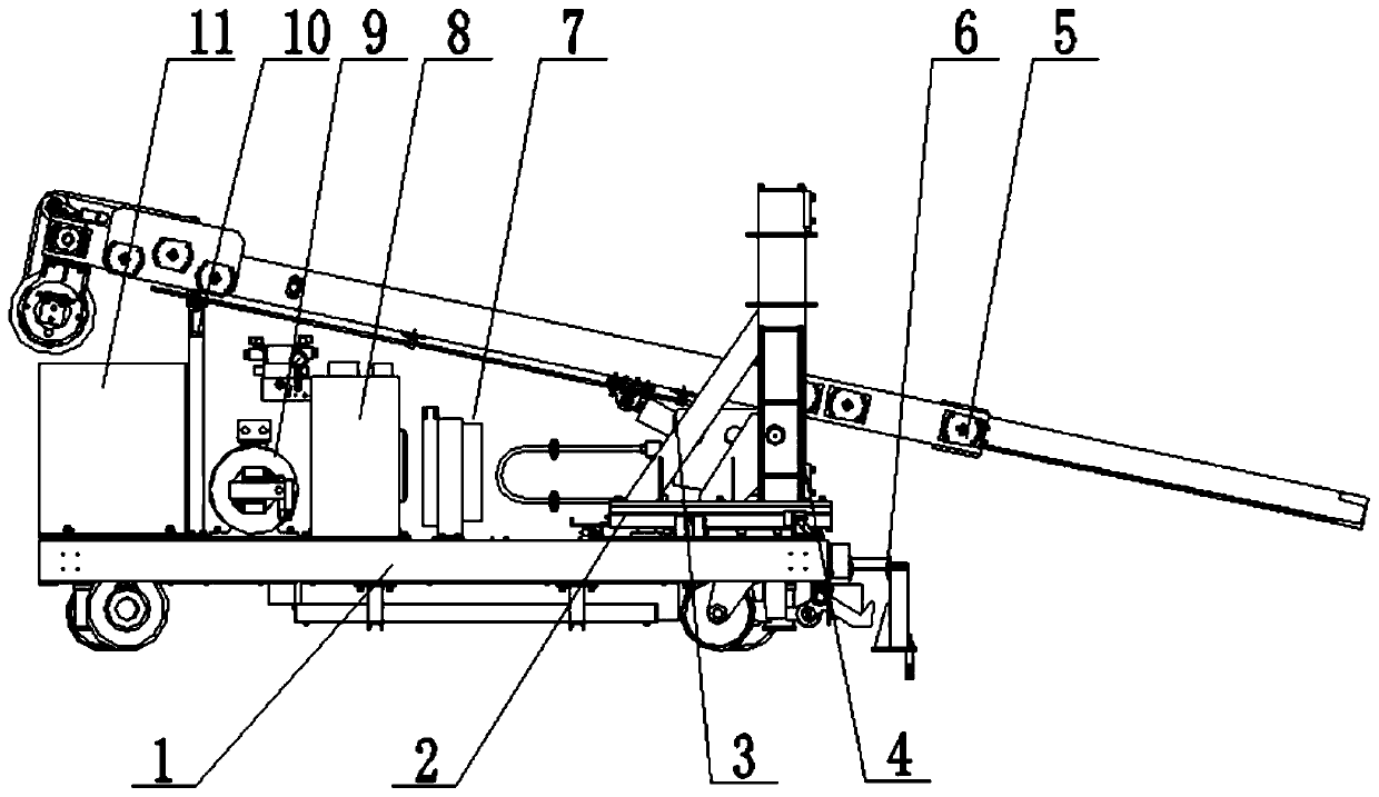
[0038] Such as Figure 1 to Figure 15 As shown, an automatic calcium carbide furnace robot according to the present invention includes a walking vehicle 1, a rotating mechanism 2, a pitch support mechanism 3, a lifting guide mechanism 4 and a drill rod driving mechanism 5;

[0039] The trolley 1 is provided with a rotary mechanism 2, the rotary mechanism 2 is provided with a lift guide mechanism 4, the pitch support mechanism 3 is slidably arranged on the lift guide mechanism 4, one end of the drill rod drive mechanism 5 is placed on the trolley 1, and the drill rod The middle part of the drive mechanism 5 is hinged with the pitch support mechanism 3 .

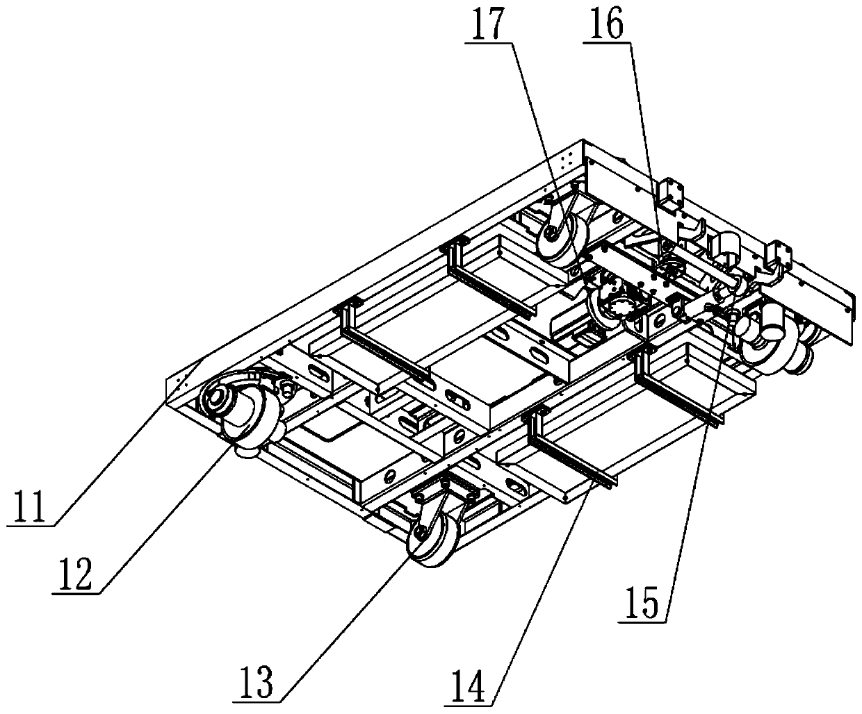
[0040] Further: the trolley 1 includes a vehicle frame, a steering wheel 12, a universal wheel 13, a battery support 14, a hydraulic hook mechanism 15, a press rotary joint 16 and a rotary dri...


PUM


Abstract

The invention discloses an automatic calcium carbide stoking robot, and belongs to the technical field of calcium carbide furnace stoking. The automatic calcium carbide stoking robot aims to solve theproblems of poor maneuvering performance, small operation range and low drill rod freedom degree of a conventional stoking robot. The automatic calcium carbide stoking robot comprises a travelling vehicle, a rotating mechanism, a pitching supporting mechanism, a lifting guide mechanism and a drill rod driving mechanism; the rotating mechanism is arranged on the travelling vehicle, the lifting guide mechanism is arranged on the rotating mechanism, the pitching supporting mechanism is arranged on the lifting guide mechanism in a sliding mode, and the middle of the drill rod driving mechanism ishinged to the pitching supporting mechanism. According to the automatic calcium carbide stoking robot, the position can be conveniently, freely and flexibly adjusted, and a drill rod can conduct stoking operation on a calcium carbide furnace in a large range.

Description

technical field [0001] The invention relates to a furnace stamping robot, in particular to an automatic calcium carbide furnace stamping robot, which belongs to the technical field of calcium carbide furnace stamping. Background technique [0002] The calcium carbide furnace robot works on the second floor of the calcium carbide workshop. It is used to pry, vibrate, and break the hard shell of the material surface in the furnace at the door of the calcium carbide furnace. The traditional furnace robot can only move forward or backward. Poor, and the range of motion of the drill rod is small, in order to increase the working range of the drill rod, the position of the whole furnace robot can only be continuously moved. Contents of the invention [0003] The purpose of the present invention is to provide an automatic calcium carbide furnace robot to solve the problems of poor maneuverability, small working range and low degree of freedom of chisel rods of traditional furnace...

Claims


Application Information

Patent Timeline
IPC IPC(8): F27D25/00
CPCF27D25/001
Inventor 倪红军刘相元刘延杰吴明月奚泉李洪亮
Owner HARBIN BOSHI AUTOMATION
Learn More