
Steel structure beam

A technology of steel structure beams and steel beams, applied in truss structures, joists, girders, etc., can solve problems such as insufficient stability, and achieve the effects of increasing stability performance, increasing bearing capacity, and increasing elastic loads

Active Publication Date: 2020-07-14
湖北楚天大地建设工程有限公司
View PDF7 Cites 0 Cited by
  • Summary
  • Abstract
  • Description
  • Claims
  • Application Information

AI Technical Summary

Problems solved by technology

[0004] In steel structure houses, the beam structure is essential and must have sufficient bearing capacity. In terms of strength and integrity, the stability of the house structure must also be ensured. In terms of earthquake resistance, corresponding technical and structural measures should also be adopted. Domestic Invention patent CN 206971544U discloses a combined H-shaped structural steel, which can provide a combined H-shaped structural steel with adjustable use width, high structural strength and strong practicability, but it only guarantees its own structure. The overall stability is indeed insufficient, and there is a lack of steel beams with stable and earthquake-resistant structures for overall steel structure buildings in the market

Method used


Image

  • Steel structure beam
  • Steel structure beam
  • Steel structure beam

Examples

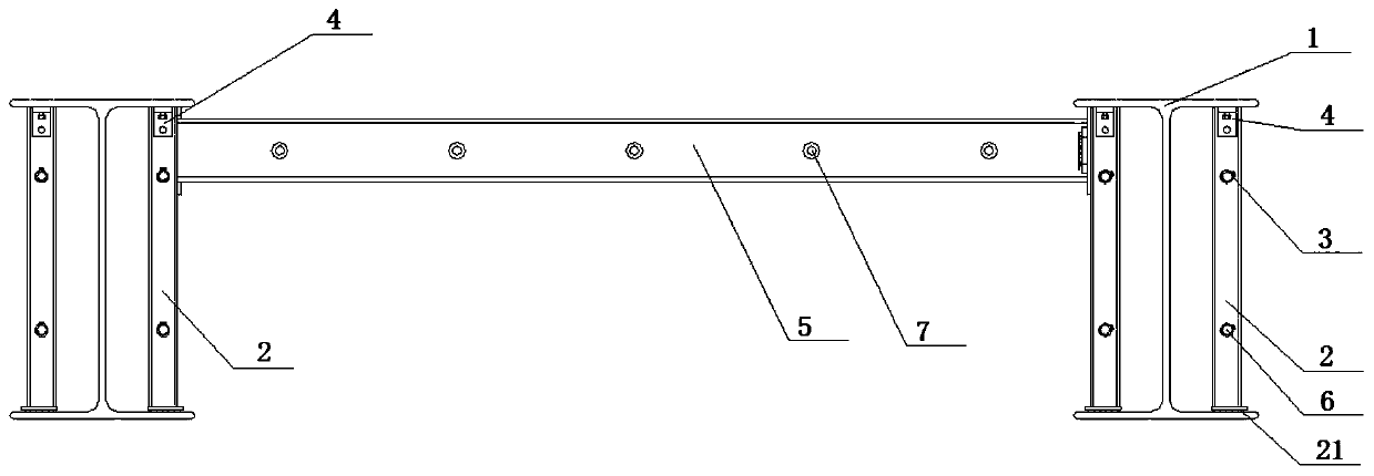
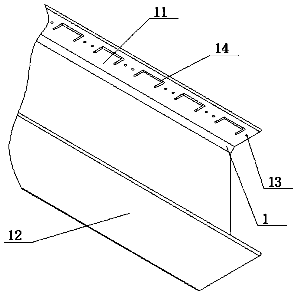
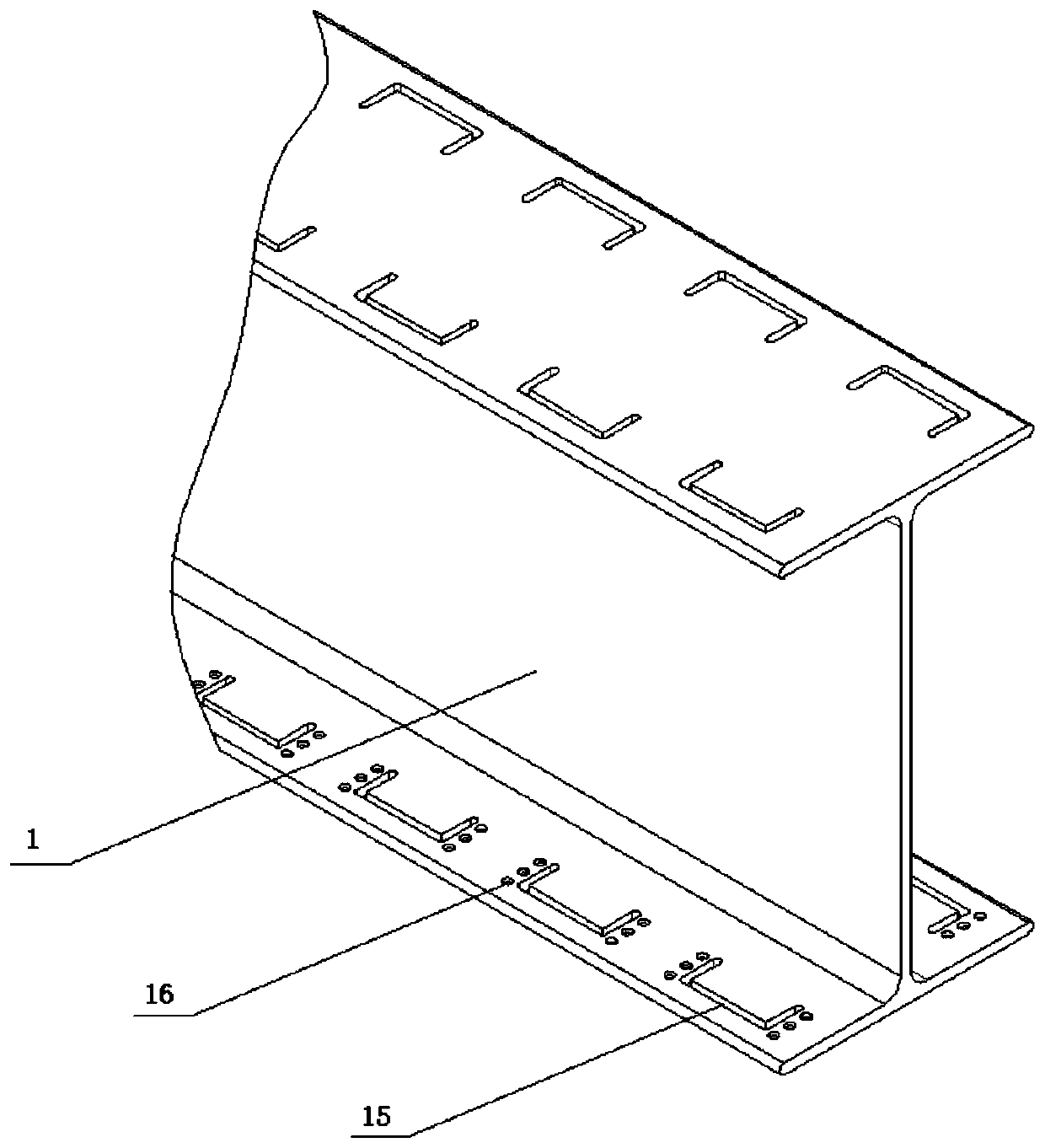

Embodiment Construction

[0026] The standard parts used in the present invention can be purchased from the market, and the special-shaped parts can be customized according to the instructions and the records of the accompanying drawings. Conventional means such as welding and clasp fastening will not be described in detail here.

[0027] refer to Figure 1-12, a specific embodiment of the present invention comprises steel beam 1, and described steel beam 1 comprises upper plate 11, and several first through grooves 14 are uniformly arranged on upper plate 11, and channel steel 2 is connected in the first through groove 14, and groove The steel 2 is provided with a second through groove 24 near the end of the upper plate 11. The second through groove 24 is nested and connected to the rafters 5. The rafters 5 are linearly and uniformly distributed along the length direction of the steel beam 1. The top of the rafter 5 is inserted into the adjacent steel beam 1. In the second through groove 24 on the up...


PUM


Abstract

The invention discloses a steel structure beam. The beam comprises a steel beam, the steel beam comprises an upper plate, multiple first through grooves are evenly formed in the upper plate, channel beams are connected into the first through grooves, second through grooves are formed in the positions, close to the end of the upper plate, of the channel beams, rafters are connected into the secondthrough grooves in an embedded manner, the top ends of the rafters are inserted into the second through grooves which are formed in the positions, on the upper portions of the channel beams, of the adjacent steel beams, the rafters corresponding to the adjacent steel beams are in embedded connection with the positions, on the upper ends of the channel beams, of the second through grooves, multiplefirst steel rib holes are formed in the two sides of the channel beams, steel rib sleeves are mounted in the first steel rib holes, two sides, away from the end of a bottom supporting plate, of the channel beams are provided with limiting holes, the sides, close to the supporting plate, of the limiting holes are provided with first thread holes, the first thread holes are connected with first fixed bolts, and the first fixed bolts are connected with L-shaped blocks through fixed holes. Shortcomings in the prior art can be overcome, and stability and vibration resisting properties of the wholesteel structure building can be improved.

Description

technical field [0001] The invention relates to the technical field of steel structure buildings, in particular to a steel structure beam. Background technique [0002] In recent years, steel structure buildings have obvious advantages in terms of energy saving, high efficiency, environmental protection and industrialization compared with brick-concrete structures. With the development of industry, steel structure components are also developing towards large-scale development. , earthquake resistance, good thermal insulation performance, dry construction, short construction period, low cost and other advantages, light steel building structures have developed rapidly in Europe and the United States, in the United States, Canada, Australia, Japan, Sweden and other countries, the steel structure in Steel consumption has accounted for more than 30% of steel production, steel structure buildings account for more than 40% of the total residential building area, and single-story an...

Claims


Application Information

Patent Timeline
Patent Type & Authority Applications(China)
IPC IPC(8): E04C3/04E04B1/24E04B1/58
CPCE04B1/2403E04B2001/2406E04B2001/2415E04B2001/2418E04B2001/2457E04C3/04
Inventor 王升
Owner 湖北楚天大地建设工程有限公司
Learn More