Eureka AIR delivers breakthrough ideas for toughest innovation challenges, trusted by R&D personnel around the world.

Efficient punching device for mechanical part machining

A technology of mechanical parts and punching device, applied in the field of mechanical parts processing, can solve the problems of low processing efficiency, low safety, high risk of taking, and achieve the effect of fast clamping, fast feeding and punching

Inactive Publication Date: 2020-07-14
龙岩市腾兴机械维修有限公司
View PDF10 Cites 4 Cited by
  • Summary
  • Abstract
  • Description
  • Claims
  • Application Information

AI Technical Summary

Problems solved by technology

[0003] When processing mechanical parts, it is often necessary to use a punching device to punch the parts. The current punching device is generally simple in structure, and the parts need to be artificially placed on the upper end of the processing plate, and then the punching device is activated However, it is highly dangerous to take it artificially. The existing punching device is not easy to quickly feed and punch the parts, resulting in low processing efficiency and low safety.

Method used


Image

  • Efficient punching device for mechanical part machining
  • Efficient punching device for mechanical part machining
  • Efficient punching device for mechanical part machining

Examples


Embodiment 1

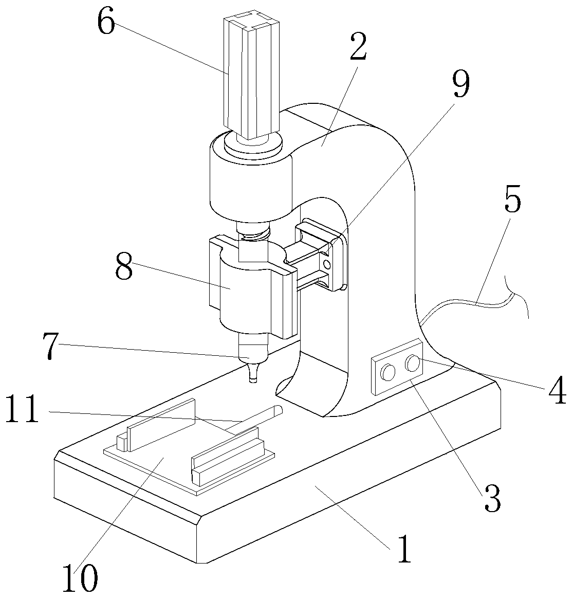
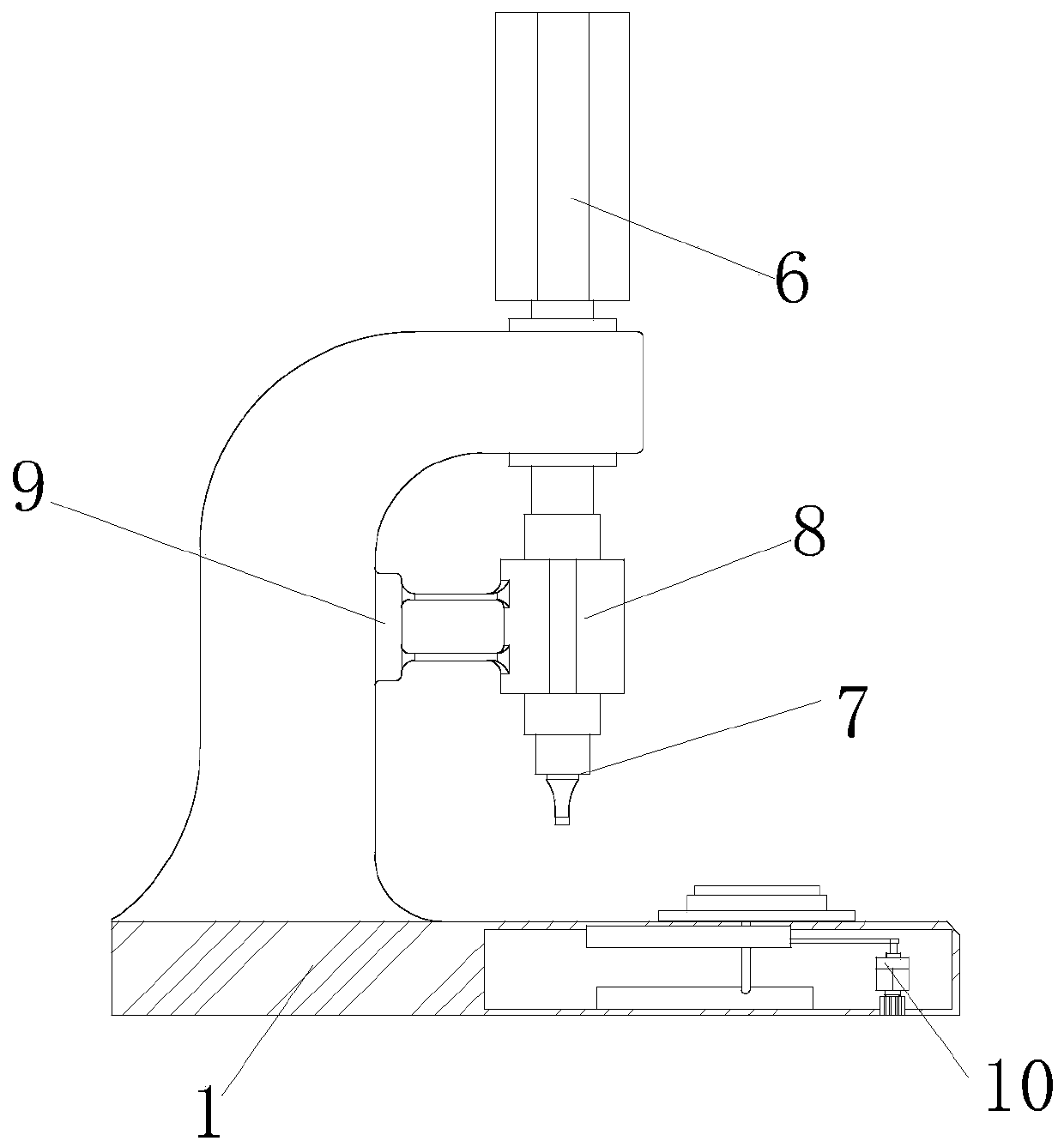
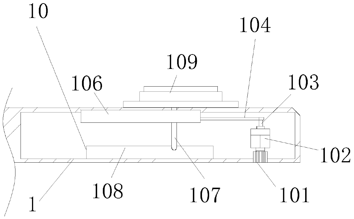
[0028] see figure 1 and figure 2 , the present invention provides a high-efficiency punching device for processing mechanical parts through improvement, including a base plate 1, an electric push rod 6, a punching head 7, a guide block 8, a support rod 9 and a reciprocating feeding mechanism 10, the base plate 1 and The bottom of the column 2 is fixed as a whole, the right end of the column 2 is provided with a control panel 3, the front end of the control panel 3 is equipped with a button 4, the rear end of the column 2 is fixed with a power wire 5, and the column 2 is locked and fixed with the bottom of the electric push rod 6 by screws, reciprocating The feeding mechanism 10 is installed and fixed on the inner right end of the bottom plate 1, the electric push rod 6 is fixedly connected with the top of the punching head 7, and the punching head 7 is slidingly matched with the inner side wall of the guide block 8, and the guide block 8 is fixedly connected with the front en...

Embodiment 2

[0032] The present invention provides a high-efficiency punching device for machining mechanical parts through improvement. The sliding shaft 107 is in the shape of a cuboid, and the sliding shaft 107 runs through the left end of the sliding block 105 and the sliding frame 106, which is beneficial to drive the loading plate 1091 to carry out For smooth movement, the inner side of the fixed block 1092 is provided with a groove, and the clamp block 1094 is embedded in the groove inside the fixed block 1092, which is conducive to the smooth movement of the clamp block 1094. The inner side of the guide block 8 is cavity-shaped, and guides The inner wall of the block 8 is smooth, which is beneficial to make the punching head 7 move smoothly.

[0033] The present invention provides a high-efficiency punching device for processing mechanical parts through improvement, and its working principle is as follows;

[0034] First, before use, place the high-efficiency punching device for me...


PUM


Abstract

The invention discloses an efficient punching device for mechanical part machining. The efficient punching device for mechanical part machining comprises a bottom plate, an electric push rod, a punching head, a guide block, a supporting rod and a reciprocating feeding mechanism. According to the efficient punching device for mechanical part machining, the reciprocating feeding mechanism is arranged inside the bottom plate, and a motor drives a first swing rod to swing, so that the first swing rod drives a sliding block to move on the inner side of a sliding frame through a second swing rod, the sliding block drives a sliding shaft to move at the upper end of a guide rail, the sliding shaft drives a part at the upper end of a carrying plate to be placed at the just lower end of the punchinghead to be punched, and the advantage that feeding and punching can be rapidly carried out is achieved; and a clamping plate mechanism is arranged at the upper end of the reciprocating feeding mechanism, the part is placed on the inner sides of clamping blocks, the clamping blocks can press buffer springs to generate deformation and contraction, and the clamping blocks are driven to clamp the part through elastic potential energy of the buffer springs to recover deformation, so that the advantage that the part can be rapidly clamped is achieved.

Description

technical field [0001] The invention relates to the related field of machining of mechanical parts, in particular to a high-efficiency punching device for machining of mechanical parts. Background technique [0002] Mechanical parts, also known as mechanical components, are the basic components of machinery. They are inseparable individual parts that make up machinery and machines. General term. [0003] When processing mechanical parts, it is often necessary to use a punching device to punch the parts. The current punching device is generally simple in structure. It is necessary to artificially place the parts on the upper end of the processing plate, and then start the punching device to punch. However, the risk of manual handling is high, and the existing punching device is not easy to quickly feed and punch parts, resulting in low processing efficiency and low safety. Contents of the invention [0004] Therefore, in order to solve the above-mentioned shortcomings, th...

Claims


Application Information

Patent Timeline
IPC IPC(8): B21D28/24B21D43/10F16F15/067
CPCB21D28/24B21D43/10F16F15/067
Inventor 刘汉武
Owner 龙岩市腾兴机械维修有限公司
Why Eureka
Eureka Blog
Learn More