Eureka AIR delivers breakthrough ideas for toughest innovation challenges, trusted by R&D personnel around the world.

Photocatalytic device

A photocatalyst and light irradiation technology, applied in physical/chemical process catalysts, household refrigeration devices, metal/metal oxide/metal hydroxide catalysts, etc. Complex structure and other problems, to achieve the effect of improving the degree of freedom, suppressing heat generation, and simplifying the structure

Pending Publication Date: 2020-07-10
JAPAN
View PDF6 Cites 0 Cited by
  • Summary
  • Abstract
  • Description
  • Claims
  • Application Information

AI Technical Summary

Problems solved by technology

Thus, in the existing photocatalyst device, on both sides of the photocatalyst filter, the flow path on the inlet side and the flow path on the outlet side of the vent hole are used to make gas (gas) pass through each filter without stagnation. The entire area of ​​the filter surface must be set on the opposite side, and the device size in the thickness direction of the filter becomes large
[0004] Moreover, in the flow path on the inlet side or the outlet side, an irradiation part for irradiating the filter surface with light must also be provided, and the irradiation part must not hinder the flow of gas. The structure of light irradiation with gas flow resistance tends to become complicated, which becomes a cause of cost increase, and there is a limit in improving the efficiency of light irradiation, and the power consumption to ensure the amount of light irradiation increases, and the amount of heat generated also increase the problem

Method used


Image

  • Photocatalytic device
  • Photocatalytic device
  • Photocatalytic device

Examples


Embodiment Construction

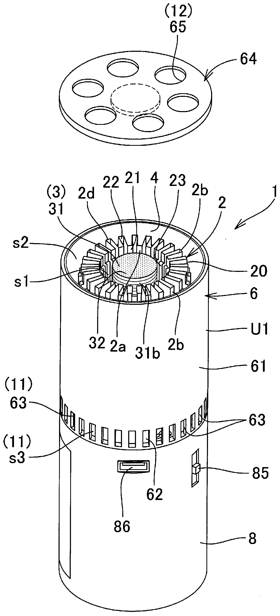
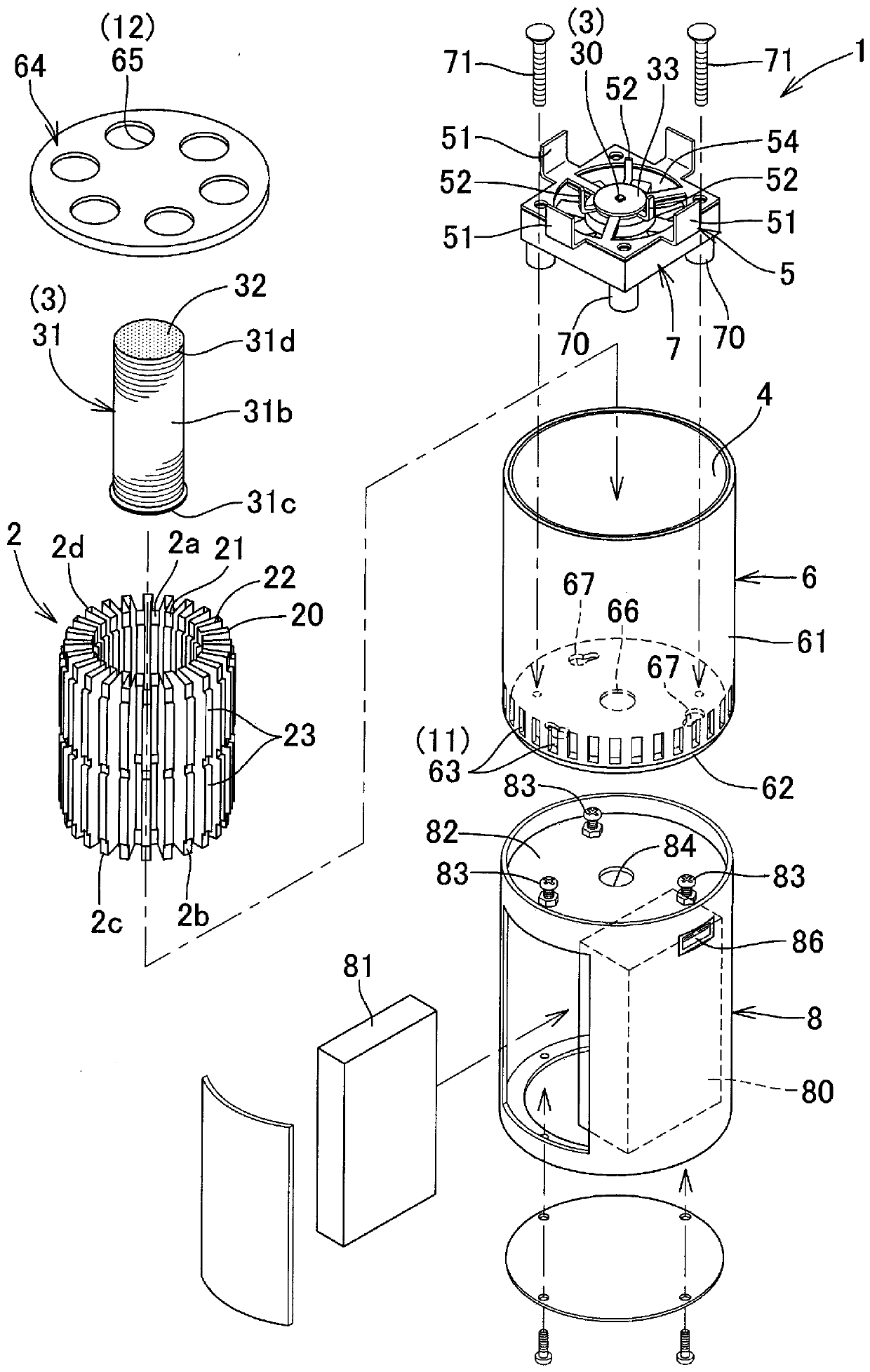
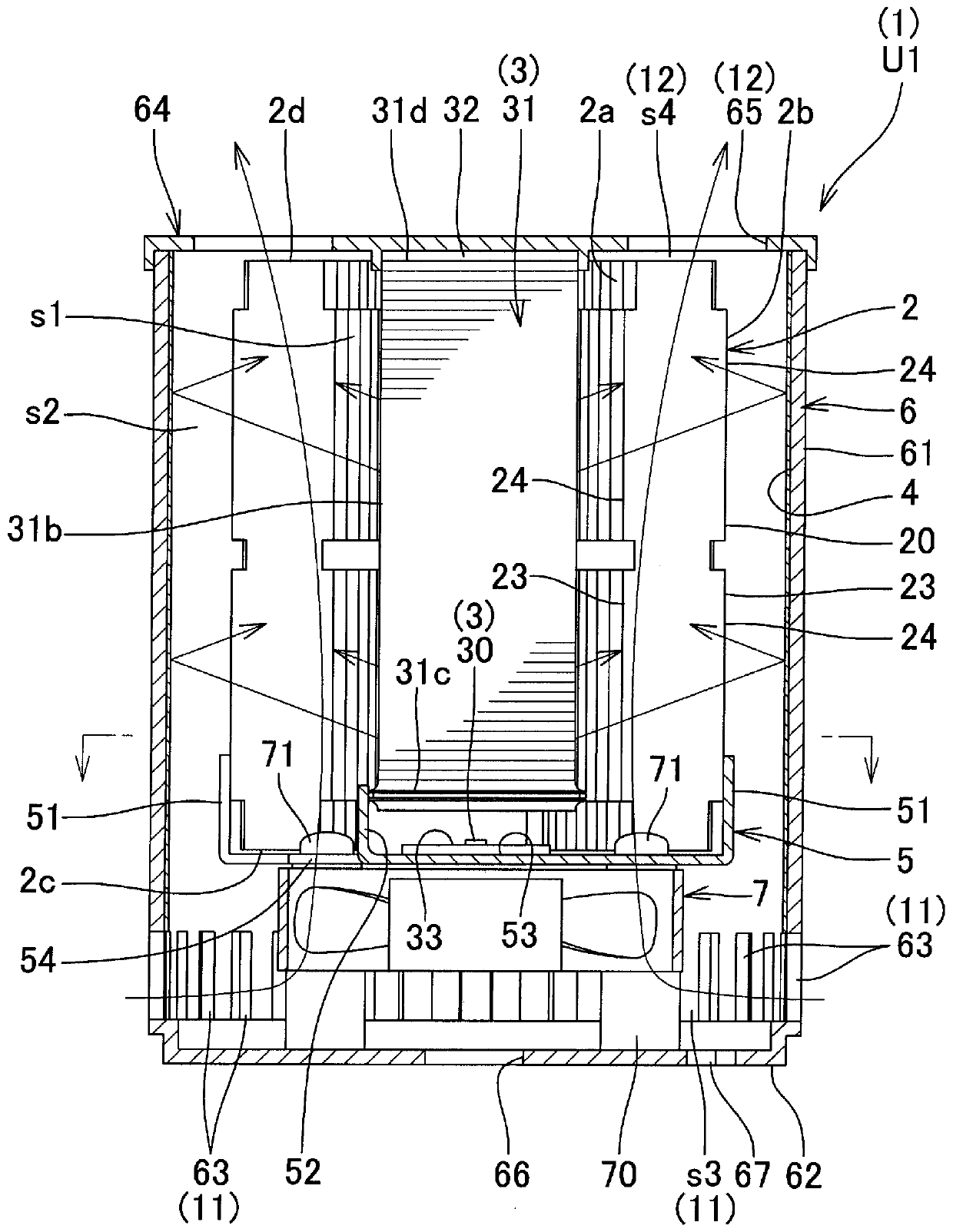
[0045] Next, embodiments of the present invention will be described in detail based on the drawings. First, based on Figure 1-10 , and the first embodiment will be described.

[0046] The photocatalyst device 1 of the present invention is as Figure 1 to Figure 4 As shown, it includes: a component 20 having a waveform having a plurality of peaks 21 and valleys 22 alternately formed, and light beams for passing ultraviolet or visible light are respectively formed at the tops of the peaks 21 and the bottoms of the valleys 22 . Through the hole 23, the photocatalyst filter 2 carrying a photocatalyst on the surface; the photoirradiation part 3 that irradiates the light of ultraviolet rays or visible light to one surface 2a of the inner and outer surfaces of the photocatalyst filter 2; On the opposite side of the other face 2b of the filter 2, the reflective wall 4 that is irradiated from the light irradiation part 3 and passed through the light passage hole 23 of the photocatal...


PUM


Abstract

In the present invention, a photocatalytic device is formed by providing a gas inflow part and a gas outflow part for a gas at both end positions of a photocatalytic filter instead of providing a gasinlet-side flow channel and a gas outlet-side flow channel at positions facing the filter surface, while maintaining the contact area between the gas and the filter surface by adopting a waveform member as the photocatalytic filter and causing the gas to flow in the direction in which the ridges and valleys extend, over the front and rear surfaces of the filter from one end to the other end. Accordingly, there is no increase in flow resistance of the gas, the device can be made smaller by thinning the device, reducing the diameter, or the like, light irradiation efficiency can be improved, energy consumption and costs can be reduced, and the problem of heat can be resolved with a simple structure.

Description

technical field [0001] The present invention relates to a photocatalyst device including a photocatalyst filter carrying a photocatalyst, and a photoirradiation unit for irradiating ultraviolet light or visible light to the surface of the photocatalyst filter. Background technique [0002] As such a photocatalyst device, the following photocatalyst device is proposed, which includes: a box in which gas can flow; a photocatalyst filter arranged in the box; and a light irradiation unit having a plurality of light emitting diodes mounted on a substrate. On the other hand, the first and second irradiation units that irradiate the surface of the photocatalyst filter with light are alternately arranged side by side (for example, refer to Patent Document 1). [0003] Like this, the existing photocatalyst device all is to light-irradiate the filter surface of the photocatalyst filter while allowing gas (gas) to pass through the air hole of the photocatalyst filter, and the photocata...

Claims


Application Information

Patent Timeline
Patent Type & Authority Applications(China)
IPC IPC(8): B01J35/02A61L9/00A61L9/18B01J21/06B01J23/30B60H3/00F25D23/00
CPCA61L9/205B01J35/004B60H3/06B60H2003/0675
Inventor 渡边辉夫渡边秀满渡边泰之渡边刚文
Owner JAPAN
Why Eureka
Eureka Blog
Learn More