Lamp control device and method
A control device and control method technology, applied in the direction of electrical components, etc., can solve the problems of equipment differential frequency flickering bright and dark grid imaging, affecting the service life of the drive chip, burning the chip, etc., to reduce hardware requirements, simple structure, reduce The effect of power consumption
- Summary
- Abstract
- Description
- Claims
- Application Information
AI Technical Summary
Problems solved by technology
Method used
Image

Examples
Embodiment 1
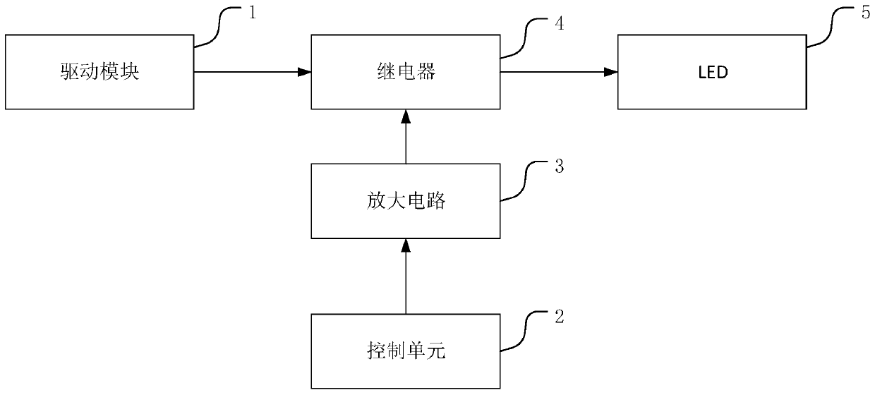
[0026] refer to figure 1 , shows a lamp control device, suitable for controlling multiple lamps, including: a drive module 1, a control unit 2, an amplification circuit 3, a relay 4 and an LED5; The current is amplified to a specified value; the relay 4 is turned on based on the amplified control signal, so that the driving module is electrically connected to the corresponding LED 5 .
[0027] Among them, the LED driver module, the normal control of each channel of light, must have a corresponding driver module. Generally, it is controlled by a PWM (pulse width modulation) signal. By changing the duty cycle, the current size of the drive output is controlled, and the brightness of the lamp bead is finally controlled.
[0028] The control unit is a small control center, which can mainly be a simple control structure such as a single-chip DSP circuit, and its purpose is to choose which lamp to light.
[0029] The amplifying circuit is the basic circuit; the relay is used for t...
Embodiment 2
[0041] On the basis of the relay, an additional switch (MOS tube) can be added. The power supply requirement of the LED is generally 12V\24V; while the high level of the control (signal) directly output by the microcontroller\DSP circuit is 1.8V or 3.3V; that is, MOS The tube will be in a normally on state and cannot realize the switch function.
[0042] Use a triode to convert the level of the enable signal output by the controller to 12V\24V (ie level conversion), and generate a level change of 0V-12V\24V, thereby enabling the on and off of the MOS tube (ie switch to switch).
[0043] Through two switches (MOS tube and relay), the safety of the circuit can be increased.
Embodiment 3
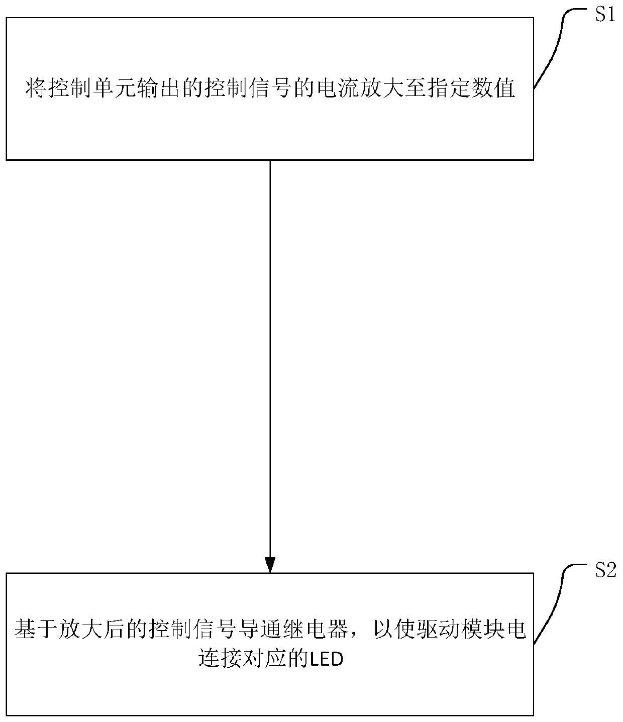
[0045] refer to image 3 , shows a lighting control method, applicable to the above lighting control device, comprising:
[0046] S1. Amplify the current of the control signal output by the control unit to a specified value;
[0047] S2. Turn on the relay based on the amplified control signal, so that the driving module is electrically connected to the corresponding LED.
[0048] The lamp control device of the embodiment of the present invention has at least the following beneficial effects: the current of the control signal is increased by the amplifying circuit, the hardware requirements of the control unit can be reduced, and the corresponding power consumption can be reduced; the electrical connection is realized by the relay, the structure is simple, and the power consumption is low; It can reduce the requirement for heat dissipation and reduce the overall complexity of the circuit.
[0049] The lighting control method according to other embodiments of the present inven...
PUM
 Abstract
Description
Claims
Application Information
 - R&D
- Intellectual Property
- Life Sciences
- Materials
- Tech Scout
- Unparalleled Data Quality
- Higher Quality Content
- 60% Fewer Hallucinations
Browse by: Latest US Patents, China's latest patents, Technical Efficacy Thesaurus, Application Domain, Technology Topic, Popular Technical Reports.
© 2025 PatSnap. All rights reserved.Legal|Privacy policy|Modern Slavery Act Transparency Statement|Sitemap|About US| Contact US: help@patsnap.com