
Fast charging switching circuit and method based on dual-interface plugging detection

A technology for switching circuits and detecting circuits, applied in the measurement of electricity, circuit devices, and measurement of electrical variables, etc., can solve the problems that insertion is not easy to detect, the action logic cannot adapt to the actual situation, the internal circuit is complex, etc., to expand the range of detectable equipment. , scene switching is efficient and time-saving, and the effect of meeting fast charging needs

Pending Publication Date: 2020-07-10
SHENZHEN INJOINIC TECH
View PDF0 Cites 6 Cited by
  • Summary
  • Abstract
  • Description
  • Claims
  • Application Information

AI Technical Summary

Problems solved by technology

However, some detections in existing solutions are not flexible enough, the action logic cannot adapt to the actual situation, and the efficiency is low
However, those with higher efficiency have complex internal circuits, resulting in higher production costs for the required hardware circuits.
[0003] In the technical solution of the prior art 1, the A and C ports are not independent, and only support 5V charging when the dual-port NMOS is turned on, and re-awakening the fast charging requires plugging and unplugging, which is not flexible enough to switch according to the corresponding scenario
[0004] In the technical solution of prior art 2, ports A and C are independent, and the two ports work separately. When the two ports are inserted, both ports A and C can perform fast charging, but the production cost is relatively high
[0005] Therefore, for some low-current devices, if the corresponding NMOS is turned off when plugged in, the plug-in is not easy to detect; when the dual-port NMOS is turned on, only 5V charging can be performed, and the load cannot be flexibly detected; the cost is high and the space occupied larger

Method used


Image

  • Fast charging switching circuit and method based on dual-interface plugging detection
  • Fast charging switching circuit and method based on dual-interface plugging detection
  • Fast charging switching circuit and method based on dual-interface plugging detection

Examples


Embodiment Construction

[0031] In order to make the object, technical solution and advantages of the invention clearer, the present invention will be further described in detail below in conjunction with the accompanying drawings and embodiments. It should be understood that the specific embodiments described here are only used to explain the present invention, and are not limited to the present invention.

[0032] An embodiment of a fast-charging switching circuit based on dual-interface plug-and-plug detection:

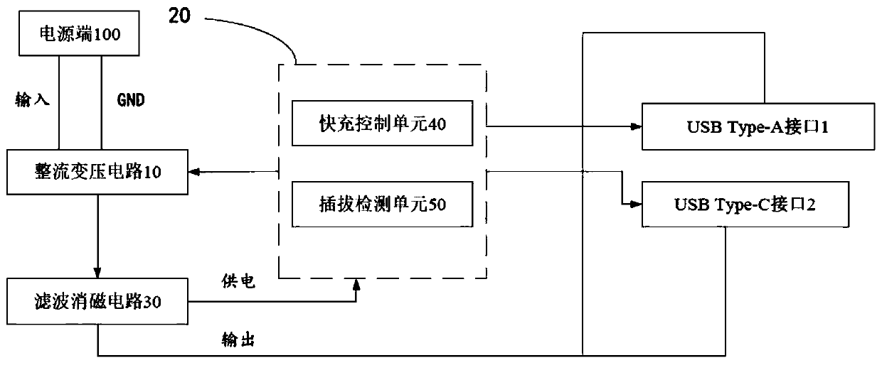
[0033] join figure 1 , a fast charging switching circuit based on dual-interface plug-and-plug detection of the present invention includes a power supply terminal 100, a rectification and transformation circuit 10, a control system 20, a USB Type-A interface 1, and a USB Type-C interface 2, and the power supply terminal 100 inputs The power supply voltage is supplied to the rectification and transformation circuit 10, and a filtering and degaussing circuit 30 is connected between the rect...


PUM


Abstract

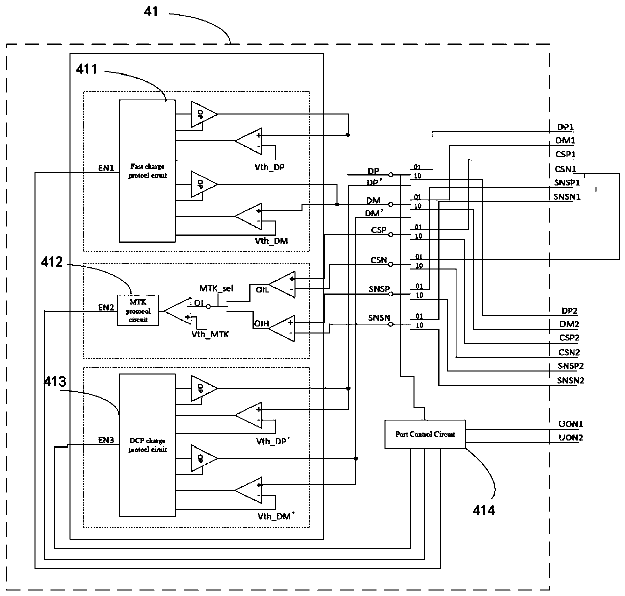
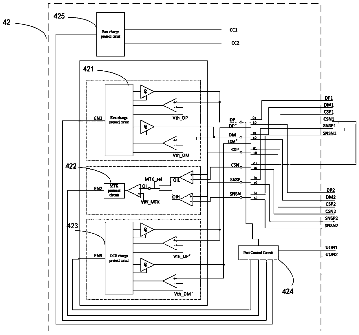
The invention discloses a fast charging switching circuit and method based on dual-interface plugging detection. The circuit comprises a power supply end, a rectification transformation circuit, a control system, a USB Type-A interface and a USB Type-C interface. A filtering degaussing circuit is connected between the rectification transformation circuit and the USB Type-A interface and between the rectification transformation circuit and the USB Type-C interface. The USB Type-A interface and the USB Type-C interface are connected with a switch unit. The control system is connected between therectification transformation circuit and the USB Type-A interface as well as between the rectification transformation circuit and the USB Type-C interface, and the control system comprises a fast charging control unit and a plugging detection unit. The method is applied to the circuit. According to the invention, the design cost of the circuit can be saved, the detectable equipment range is expanded, the scene switching is more efficient and time-saving, and the quick charging requirement is better met.

Description

【Technical field】 [0001] The present invention relates to the technical field of fast charging, in particular to a fast charging switching circuit based on dual-interface unplugging detection and a fast charging switching method applied to the circuit. 【Background technique】 [0002] In recent years, with the development of fast charging technology, more and more USB interface forms have emerged. As the latest interface form technology, TYPE-C is powerful and easy to use. In the current situation of more and more electronic devices, it is sometimes necessary to charge multiple electronic devices. In order to better take into account different USB interface forms, there are many dual-port charging solutions on the market. However, the existing schemes are not flexible enough for some detections, the action logic cannot adapt to the actual situation, and the efficiency is low. However, those with higher efficiency have complex internal circuits, resulting in higher manufactur...

Claims


Application Information

Patent Timeline
Patent Type & Authority Applications(China)
IPC IPC(8): H02J7/00H02J7/02G01R31/00
CPCG01R31/00
Inventor 陈伟丁淼王嘉懿
Owner SHENZHEN INJOINIC TECH
Learn More