Power battery tab heat dissipation system capable of exhausting waste gas

A power battery and heat dissipation system technology, applied in secondary batteries, exhaust plug devices, battery pack components, etc., can solve the problems of low thermal conductivity of diaphragm materials, large energy consumption of auxiliary components, uneven flow field, etc. Enhance the heat transfer rate, make up for dimensional tolerances, and inhibit the effect of heat diffusion

Active Publication Date: 2020-07-10
HARBIN ENG UNIV
View PDF10 Cites 1 Cited by
  • Summary
  • Abstract
  • Description
  • Claims
  • Application Information

AI Technical Summary

Problems solved by technology

The air-cooled thermal management system has simple structure, small space occupation, light weight, low cost, low energy consumption, no harmful gas volume pressure, and easy maintenance, but the air thermal conductivity is low, the convective heat transfer coefficient is small, the time required for heat dissipation is long, and the Large outlet pressure difference, uneven flow field, poor temperature uniformity, high discharge rate and poor cooling effect
The liquid-cooled heat management method has large specific heat capacity, high thermal conductivity, large heat transfer coefficient, thin boundary layer, strong heat transfer capacity, integrated heat dissipation and preheating, and good temperature uniformity, but it is large in size, heavy in weight, easy to leak, and expensive High, high sealing and insulation requirements (direct liquid cooling), high energy consumption of auxiliary components, complex system
[0004] At present, the vast majority of power batteries are composed of positive electrodes, diaphragms, negative electrodes and battery casings, and the thermal conductivity of the diaphragm material is low, and the thermal resistance from the inside of the cell to the vertical surface is large, and the thermal conductivity is poor. bad

Method used


Image

  • Power battery tab heat dissipation system capable of exhausting waste gas

Examples


Embodiment Construction

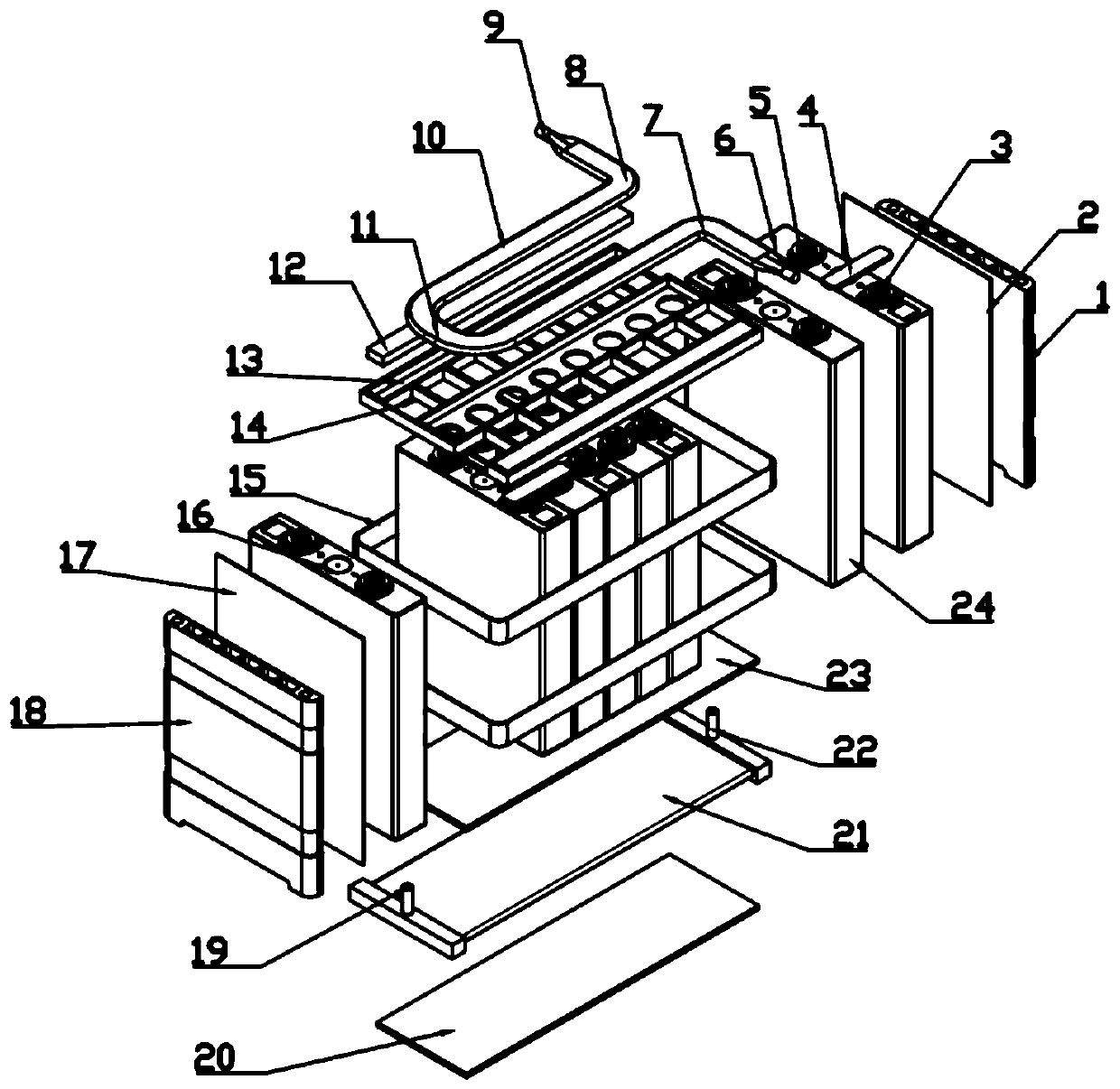
[0017] The present invention is described in more detail below in conjunction with accompanying drawing example:

[0018] combine figure 1 , the present invention provides a power battery tab heat dissipation system that can exhaust exhaust gas. On the basis of not changing the original heat management system, it combines the advantages of air cooling and liquid cooling heat management methods, effectively solving the traditional liquid cooling heat management method The disadvantage of being unable to exhaust the exhaust gas generated in the thermal management system; at the same time, using the thermal management method of battery tab heat dissipation can efficiently dissipate heat from the battery module and further improve the temperature uniformity of the system; multi-layer safety protection is set in the system, It can better avoid the current frequent battery thermal runaway problem and promote the development of new energy hybrid and pure electric vehicles.

[0019] ...


PUM


Abstract

The invention aims to provide a power battery tab heat dissipation system capable of exhausting waste gas. The power battery tab heat dissipation system comprises a battery cell, a tab air cooling pipe, a controller, an isolation frame, a soaking film, a lower liquid cooling plate, a side heat insulation plate and a bottom heat insulation pad. An isolation frame is arranged at the top of the grouped cells; a lower liquid cooling plate is arranged at the bottom; a pressure relief channel is arranged above the safety valve; heat-conducting insulating silica gel is arranged in the heat-conductingglue filling groove in the isolation frame; a tab air cooling pipe is arranged right above the positive tab and the negative tab; a soaking film is arranged between the tab air cooling pipe and the tab busbar; an exhaust valve is arranged on the air cooling pipe, and a gas sensor is arranged in the module space. Based on heat dissipation of the positive and negative tabs, advantage complementation of air cooling and liquid cooling is realized, and the heat management system is high in space utilization rate, small in heat exchange resistance and good in cooling effect; meanwhile, waste gas inthe system can be exhausted, thereby realizing high practicability.

Description

technical field [0001] The invention relates to a power battery thermal management system. Background technique [0002] In recent years, accidents such as smoke, spontaneous combustion, and fire of new energy vehicles have occurred frequently. development in the direction of globalization and long cycle life. [0003] In new energy vehicle safety accidents, thermal management issues are highlighted. The air-cooled thermal management system has simple structure, small space occupation, light weight, low cost, low energy consumption, no harmful gas volume pressure, and easy maintenance, but the air thermal conductivity is low, the convective heat transfer coefficient is small, the time required for heat dissipation is long, and the The outlet pressure difference is large, the flow field is uneven, the temperature uniformity is poor, and the cooling effect of high discharge rate is poor. The liquid-cooled heat management method has large specific heat capacity, high thermal...

Claims


Application Information

Patent Timeline
IPC IPC(8): H01M10/613H01M10/625H01M10/653H01M10/6561H01M10/6567H01M10/658H01M2/12
CPCH01M10/613H01M10/625H01M10/653H01M10/6561H01M10/6567H01M10/658H01M50/30Y02E60/10
Inventor 范立云李奎杰徐荣马龙冯力东尹冰倩
Owner HARBIN ENG UNIV
Why Eureka
Try Eureka