High-temperature molten flow destroying unexploded ordnance system

A technology of unexploded ammunition and melt flow, applied in blasting and other directions, can solve the problems of not fully guaranteeing the normal function of ammunition, reducing the stability and safety of ammunition, and limited life of ammunition, so as to improve safety and operational efficiency, reduce Explosion hazard, highly integrated effect

Active Publication Date: 2020-07-10
北京赢和睿致科技有限责任公司
View PDF6 Cites 2 Cited by
  • Summary
  • Abstract
  • Description
  • Claims
  • Application Information

AI Technical Summary

Problems solved by technology

[0002] Ammunition is an important strategic material, which requires a certain amount of storage in normal times, and the life of ammunition is limited. When the storage time of ammunition exceeds the life of ammunition, its quality will decline, and the stability and safety of ammunition will decrease. It cannot continue to meet the needs of combat training. If this type of ammunition continues to be used, there will be a major safety hazard, and it should be dealt with in a timely manner
When using the ammunition within the warranty period, the normal function of the ammunition cannot be fully guaranteed, and sometimes unexploded ammunition may occur due to various reasons. At this time, the ammunition is in a very complicated state, and a little carelessness will cause serious consequences. It must also be dealt with in a timely manner

Method used


Image

  • High-temperature molten flow destroying unexploded ordnance system
  • High-temperature molten flow destroying unexploded ordnance system
  • High-temperature molten flow destroying unexploded ordnance system

Examples


Embodiment Construction

[0032] The present invention will be further described in detail below in conjunction with the accompanying drawings and embodiments, so that those skilled in the art can implement it with reference to the text of the description.

[0033] It should be understood that terms such as "having", "including" and "including" used herein do not exclude the presence or addition of one or more other elements or combinations thereof.

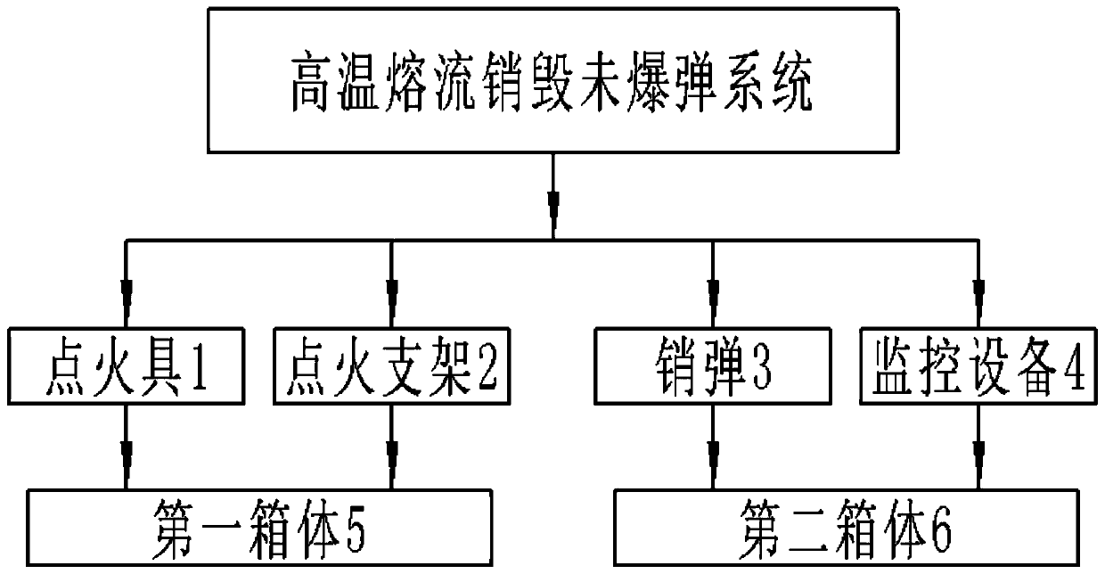
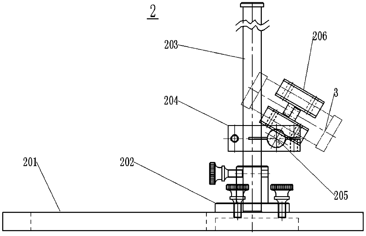
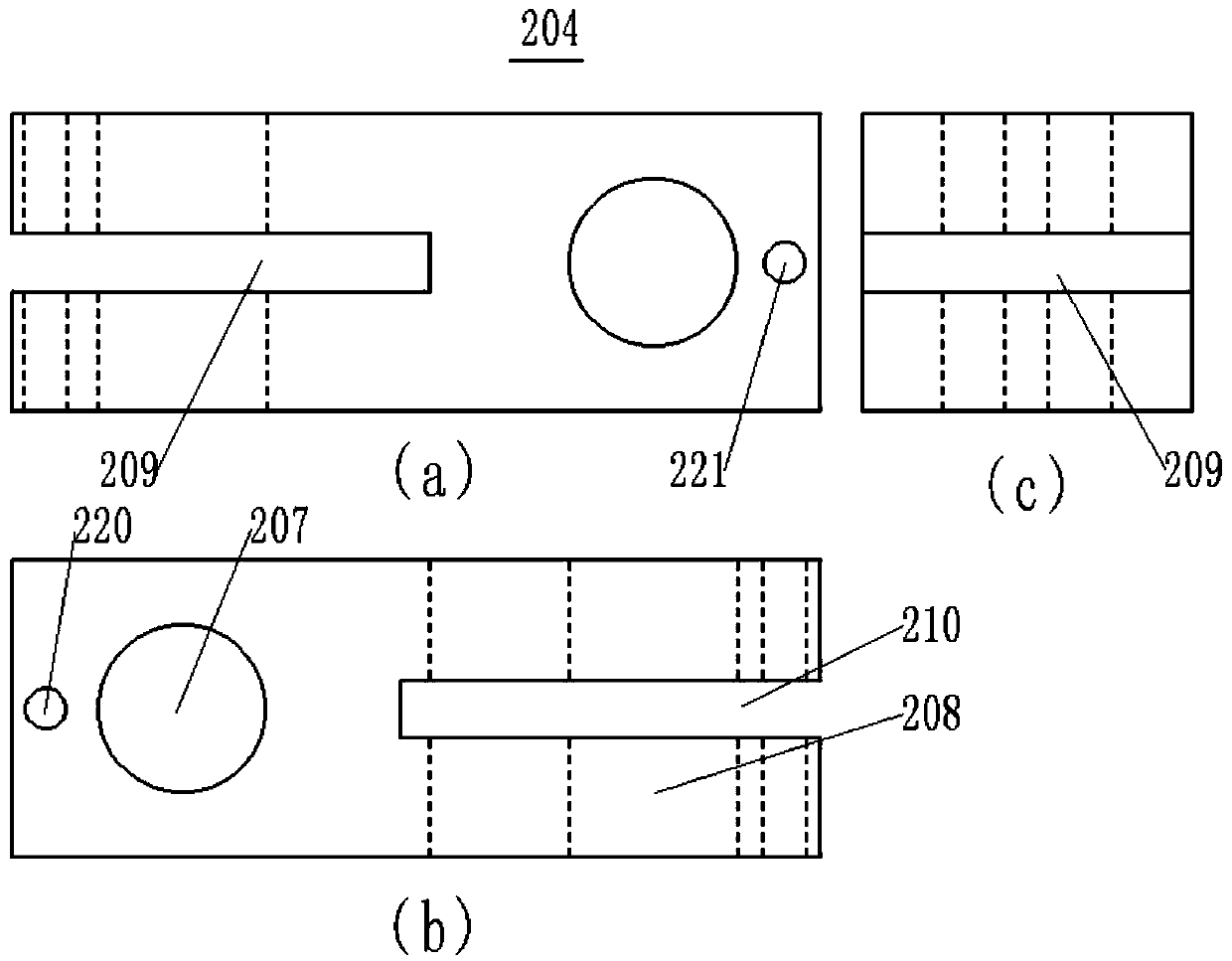
[0034] Such as figure 1 , figure 2 As shown, the present invention provides a high-temperature molten stream destroying unexploded ordnance system, including:

[0035] The ignition device 1, the ignition support 2, the pin bullet 3, and the monitoring device 4. The ignition device 1, the ignition support 2 can be selectively arranged in the first case 5, the pin bomb 3, the monitoring device 4 can be selectively arranged in the second box 6; wherein, when in use, the pin bomb 3 is erected on the ignition support 2, and the ignition device 1 is electrically conn...


PUM


Abstract

The invention discloses a high-temperature molten flow destroying unexploded ordnance system. The high-temperature molten flow destroying unexploded ordnance system comprises an igniter, an ignition bracket, destroying ammunition and monitoring equipment, the igniter and the ignition bracket is selectively arranged in a first box, and the destroying ammunition and the monitoring equipment is electively arranged in a second box; and the destroying ammunition is erected on the ignition bracket when in use, and the igniter is electrically connected with the destroying ammunition to start the destroying ammunition to destroy ammunition. The high-temperature molten flow destroying unexploded ordnance system comprises the igniter, the ignition bracket, the destroying ammunition and the monitoring equipment, the igniter and the ignition bracket can be placed in the first box, the destroying ammunition and the monitoring equipment can be placed in the second box, so that the high-temperature molten flow destroying unexploded ordnance system is high in integration level, and is convenient to carry by explosive disposal personnel; the igniter, the ignition bracket and the destroying ammunition are used for destroying the ammunition, so that the explosive disposal personnel destroy the ammunition under the condition of not being in touch with the ammunition, the explosion hazards existingin the surroundings of the explosive disposal personnel are reduced, and the safety and operating efficiency of the explosive disposal personnel are improved.

Description

Technical field [0001] The present invention relates to the technical field of ammunition destruction, and more specifically, the present invention relates to a system for destroying unexploded ordnance using a high-temperature molten stream. Background technique [0002] Ammunition is an important strategic material. It needs to have a certain amount of storage at ordinary times. The life of ammunition is limited. When the storage time of ammunition exceeds the life of ammunition, its quality condition will decline, and the stability and safety of ammunition will be reduced. Cannot continue to meet the needs of combat training, if such ammunition continues to be used, there will be greater security risks, and it should be dealt with in time. When using ammunition within the warranty period, the normal function of the ammunition cannot be fully guaranteed, and sometimes unexploded ammunition may occur due to various reasons. At this time, the ammunition is in a very complicated s...

Claims


Application Information

Patent Timeline
Patent Type & Authority Applications(China)
IPC IPC(8): F42D5/04
CPCF42D5/04
Inventor 张步俊
Owner 北京赢和睿致科技有限责任公司
Why Eureka
Try Eureka